Transient Performance Improvement for Constant On-Time Power Converters

a technology of power converter and constant ontime, which is applied in the direction of power conversion system, dc-dc conversion, instruments, etc., can solve the problems of increasing the cost of the power converter, limiting the power density, and the high clock rate of digital processor semiconductor integrated circuits operating at high clock rates. achieve the effect of improving the transient response of the power converter

Active Publication Date: 2015-10-01
VIRGINIA TECH INTPROP INC
View PDF6 Cites 57 Cited by
  • Summary
  • Abstract
  • Description
  • Claims
  • Application Information

AI Technical Summary

Benefits of technology

[0011]In accordance with another aspect of the invention, a method of improving transient response of a power converter using constant on-time or adaptive on-time control to provide power pulses to an output of the power converter is provided comprising steps of monitoring an output voltage of the power converter, (pref...

Problems solved by technology

For example, digital processor semiconductor integrated circuits operating at high clock rates may require very substantial amounts of power at very closely regulated voltage for short periods of time between possibly extended periods in a substantially stand-by state during which very little power is drawn.
However, filtering voltage changes during such transient changes in load may require very large charge storage capacity of the output filter; limiting power density and increasing cost of the power converter.
Moreover, transient response of constant on-time (COT) power converters may be largely unpredictable depending on the relative timing of a load transient and the constant duration periods during which power is drawn from the input power source.
For example, when a large increase in load power occurs, the pow...

Method used


Image

  • Transient Performance Improvement for Constant On-Time Power Converters
  • Transient Performance Improvement for Constant On-Time Power Converters
  • Transient Performance Improvement for Constant On-Time Power Converters

Examples


Embodiment Construction

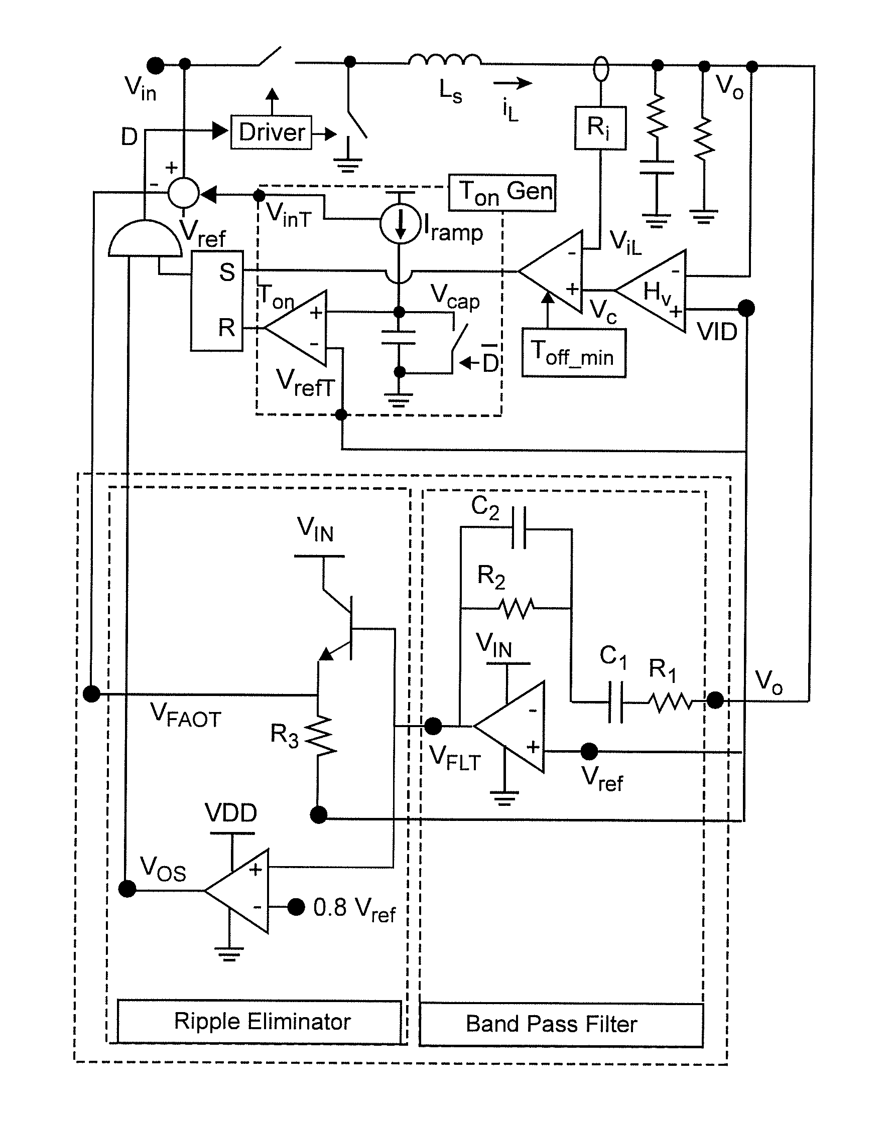
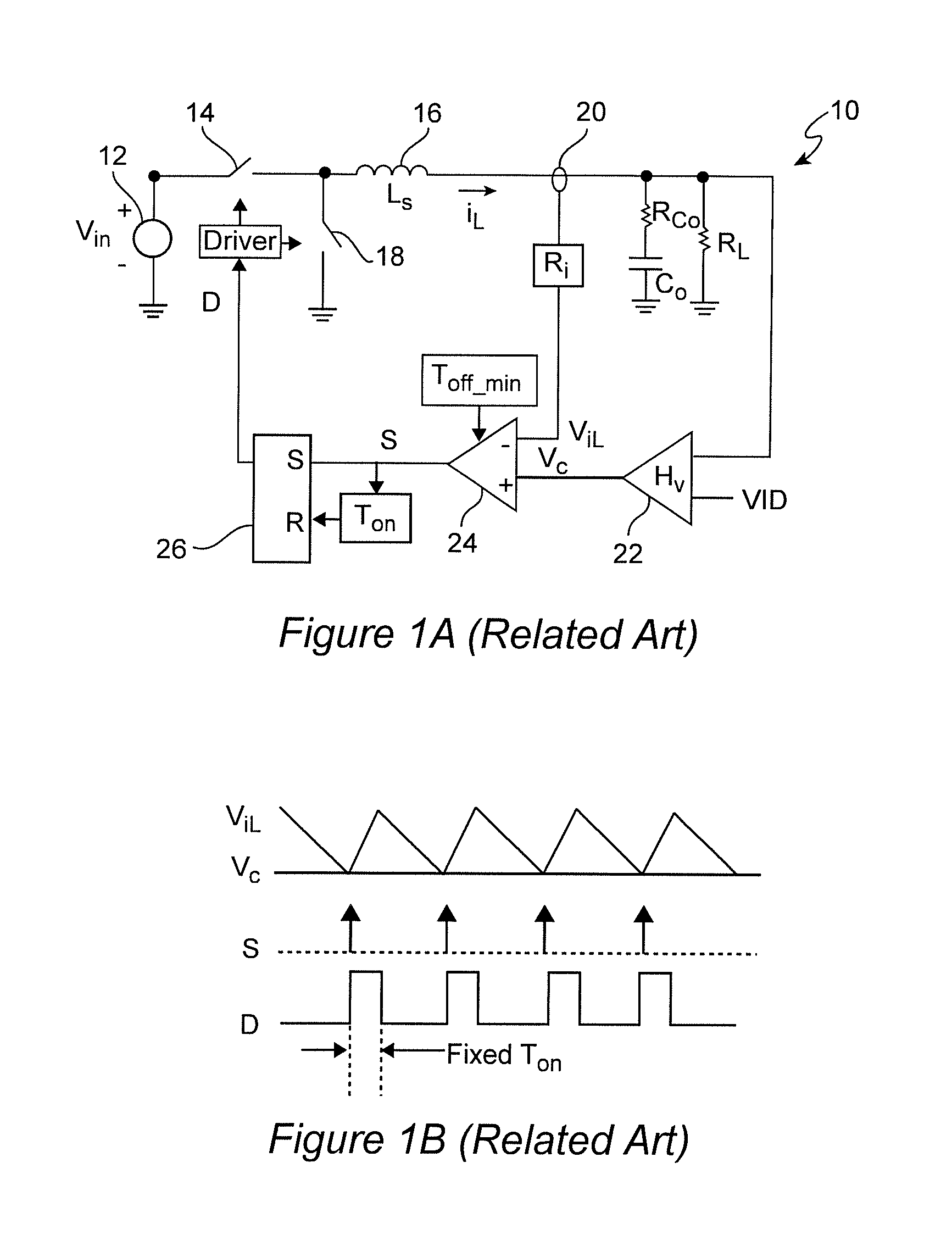
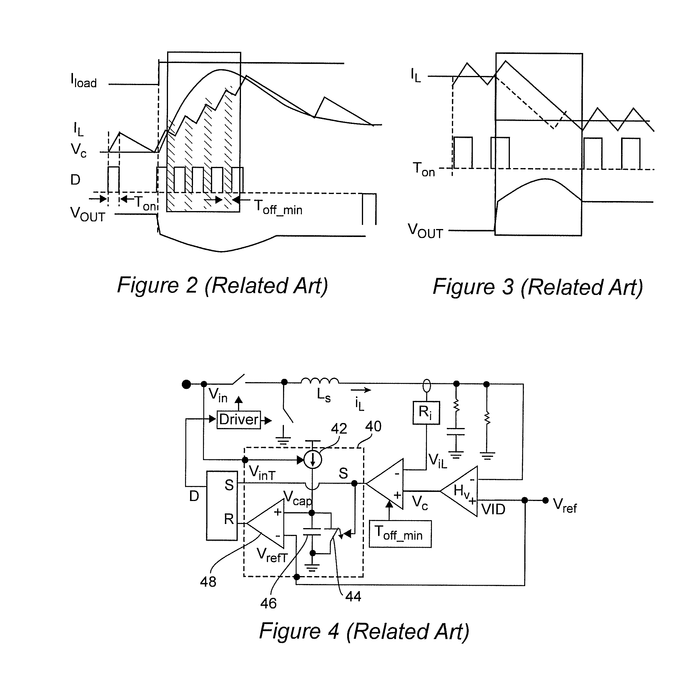
[0030]Referring now to the drawings, and more particularly to FIG. 1A, there is shown a generalized schematic diagram of an exemplary constant on-time (COT) control power converter 10 useful for understanding the transient response problem addressed by the invention which is illustrated in FIGS. 2 and 3. Operational waveforms of this power converter are illustrated in FIG. 1B. Since this schematic diagram is both generalized and arranged to facilitate an understanding of the invention, no portion of any of FIGS. 1A-3 is admitted to be prior art in regard to the invention. However, since the invention and its operation are not illustrated therein, these Figures have been labeled “Related Art”. It should also be understood that while a so-called buck converter is illustrated in these and other Figures for simplicity and general familiarity to those skilled in the art, the invention is fully applicable to any known or foreseeable power converter topology.

[0031]As is well understood in ...


PUM


Abstract

Response of a variable frequency switching constant on-time or adaptive on-time controlled power converter to a large step-up or step-down change in load is improved with a simple circuit that detects magnitude and polarity of a change in output voltage and initiates, extends or terminates conduction of power pulses from an input source through said power converter. Both the amplitude and duration of undershoot or overshoot of the transient response are reduced or, alternatively, the capacitance of an output filter may be significantly reduced and still provide comparable transient performance. The fast adaptive on-time control is applicable to multi-phase power converters using phase managers or one or more phase-locked loops for interleaving of power pulses.

Description

CROSS-REFERENCE TO RELATED APPLICATIONS[0001]This application claims benefit of priority of U.S. Provisional Patent Application 61 / 973,600, filed Apr. 1, 2014, which is hereby incorporated by reference in its entirety.DESCRIPTION[0002]1. Field of the Invention[0003]The present invention generally relates to variable frequency switching power converters and voltage regulators and, more particularly, to constant on-time power converters and voltage regulators and the improvement of transient response to changes in power delivered to a load.[0004]2. Background of the Invention[0005]Virtually all electronic apparatus including semiconductor devices require direct current power at a substantially constant voltage which may be regulated within a specified tolerance even when the current drawn by a load may vary over a wide range. For example, digital processor semiconductor integrated circuits operating at high clock rates may require very substantial amounts of power at very closely regu...

Claims


Application Information

Patent Timeline
IPC IPC(8): H02M3/156H02M1/14
CPCH02M1/14H02M3/156H02M3/1566
Inventor BARI, SYEDLEE, FRED C.LI, QIANGLIU, PEI-HSIN
Owner VIRGINIA TECH INTPROP INC
Why Eureka
Try Eureka