
Methods and nodes in a wireless communication system

Active Publication Date: 2015-10-01
HUAWEI TECH CO LTD
View PDF7 Cites 22 Cited by
  • Summary
  • Abstract
  • Description
  • Claims
  • Application Information

AI Technical Summary

Benefits of technology

The patent aims to improve wireless communication by reducing signaling overhead and efficiently transmitting data in the same subframe as broadcast information. This results in better network performance and better spectral utilization.

Problems solved by technology

The disadvantage is that its overhead is significant.
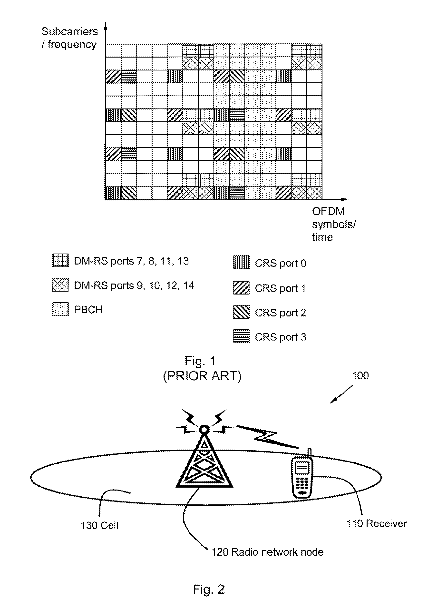
However, since the CRS is cell-specific, it cannot be receiver-specifically precoded, i.e., it cannot achieve any beamforming gains.
The prior art LTE system does not support interpolation in the time domain, since the DM-RS is only transmitted in the subframes wherein data is transmitted and such transmission may not occur in each subframe, while also different precoders may be used in different subframes.
Without the PBCH it would not be possible to access the carrier and it is therefore an open issue to provide a mechanism for transmitting broadcast information and an associated reference signal on a carrier without CRS.
However, in many cases the performance may be worse than schemes relying on transmit diversity, e.g., SFBC.
It is a problem to reliably transmit a broadcast information and / or system information while offering high spectral efficiency of a wireless communication system.
It is a further problem to define the reference signals for broadcast information transmission such that the complexity of channel estimation does not become excessive in the receiver.
It is also a problem to define the reference signals for broadcast information transmission such that the complexity of mapping other data / control channels to the time-frequency resources is not increased.
In the prior art LTE system, both CRS and DM-RS can be transmitted, which leads to high reference signal overhead, decreased throughput and reduced overall system efficiency.
Hence, it is a problem to assure that there is a reasonable trade-off between reference signal overhead and performance.

Method used


Image

  • Methods and nodes in a wireless communication system
  • Methods and nodes in a wireless communication system
  • Methods and nodes in a wireless communication system

Examples


Embodiment Construction

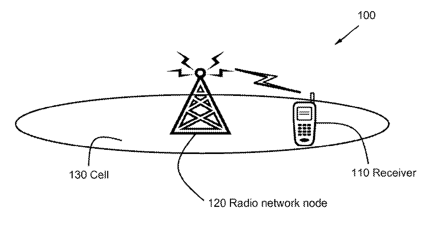
[0054]Embodiments of the invention described herein are defined as a radio network node, a method in a radio network node, a receiver and a method in a receiver, which may be put into practice in the embodiments described below. These embodiments may, however, be exemplified and realised in many different forms and are not to be considered as limited to the embodiments set forth herein; rather, these embodiments are provided so that this disclosure will be thorough and complete.

[0055]Still other objects and features may become apparent from the following detailed description considered in conjunction with the accompanying drawings. It is to be understood, however, that the drawings are designed solely for purposes of illustration and not as a definition of the limits of the herein disclosed embodiments, for which reference is to be made to the appended claims. Further, the drawings are not necessarily drawn to scale and, unless otherwise indicated, they are merely intended to concep...


PUM


Abstract

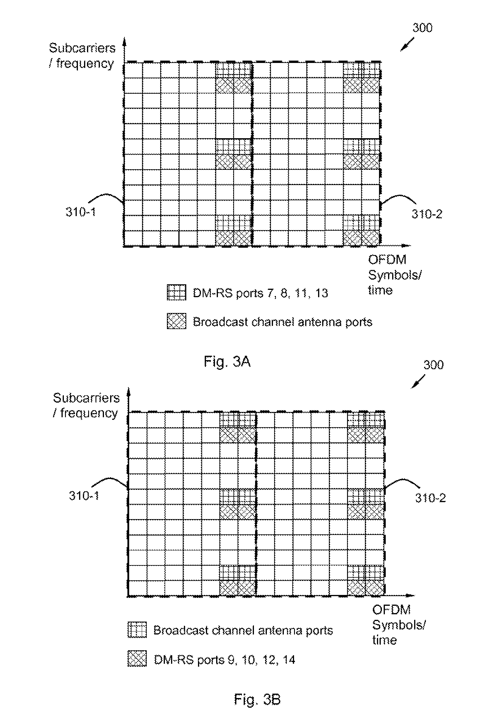
Methods (700, 900) and nodes (110, 120) for transmission of broadcast information, over at least one antenna port, in a subframe, which transmission is received by a receiver (110) in a wireless communication system (100). The broadcast information is transmitted over a set of antenna ports comprising at least one antenna port, in at least one subframe (300) comprising a set of time-frequency resources, wherein a cell-specific reference signal, CRS, is not transmitted in each subframe (300). The method (700) comprises defining (701) a set of antenna ports for the set of time-frequency resources. Also, the method (700) comprises transmitting (702) the broadcast information on the defined (701) set of antenna ports, thereby using said set of time-frequency resources exclusively, such that they are unused for any other antenna port.

Description

CROSS REFERENCE[0001]This application is a continuation of International Application No. PCT / EP2012 / 074531, filed on Dec. 5, 2012, which is incorporated herein by references in its entirety.FIELD OF INVENTION[0002]Implementations described herein relate generally to a radio network node, a method in a radio network node, a receiver and a method in a receiver. In particular is herein described a mechanism for transmission of broadcast information, from the radio network node to the receiver, using a set of time-frequency resources exclusively associated with a set of antenna ports for transmission of information.BACKGROUND OF INVENTION[0003]A receiver, also known as User Equipment (UE), mobile station, wireless terminal and / or mobile terminal is enabled to communicate wirelessly in a wireless communication system, sometimes also referred to as a cellular radio system. The communication may be made, e.g., between two receivers, between a receiver and a wire connected telephone and / or ...

Claims


Application Information

Patent Timeline
IPC IPC(8): H04L5/00H04W72/00
CPCH04L5/0023H04L5/005H04W72/005H04W72/30
Inventor BERGGREN, FREDRIKSUN, WEIJUN
Owner HUAWEI TECH CO LTD
Learn More