
Method for Image Processing and Method that Can be Performed Therewith For the Automatic Detection of Objects, Observation Device and Method for High-Precision Tracking of the Course Followed by Launched Rockets over Large Distances

Active Publication Date: 2015-10-01
AIRBUS DEFENCE & SPACE
View PDF0 Cites 5 Cited by
  • Summary
  • Abstract
  • Description
  • Claims
  • Application Information

AI Technical Summary

Benefits of technology

The system described in the patent allows for observation of rockets and other objects in space without needing to suppress false targets. A telescope and image recording device capture images, and an evaluation function is used to recognize characteristic values. This function helps limit the number of rotational positions to be examined without losing separation sharpness. Overall, the system can provide more efficient and accurate information about objects in space.

Problems solved by technology

Even if optical observation apparatuses having long focal length lenses and high-resolution image sensors are used, it is not possible to obtain high-resolution images reproducing the engine jet flame object with sharp focus within the range of a few meters at an object distance of more than 500 km to as much as 1500 km, because the brightness distribution within the jet flame fluctuates in all directions, at high frequency, in a range of up to 100 m. In spite of such reduced imaging performance, however, it must be possible to determine whether the detected object is a military or civilian launch vehicle or a decoy.
This not only requires great effort and expenditure, but is frequently also not sufficiently possible for political reasons.
Furthermore, such radar stations can only determine the position of target objects and measure their radar reflection cross-section at a distance of 1000 km crosswise to the viewing direction, with a precision of several kilometers, but cannot undertake any precise identification.
Decoys, in particular, can usually not be distinguished from true warheads by means of radar, and this causes great problems.
Because the discovery from above must take place against the warm earth background, with a great number of false targets that are difficult to recognize, these systems must battle against comparatively low sensitivity.
As a result, its measurement accuracy is limited to a few hundred meters, and cannot be significantly improved due to system limitations.

Method used


Image

  • Method for Image Processing and Method that Can be Performed Therewith For the Automatic Detection of Objects, Observation Device and Method for High-Precision Tracking of the Course Followed by Launched Rockets over Large Distances
  • Method for Image Processing and Method that Can be Performed Therewith For the Automatic Detection of Objects, Observation Device and Method for High-Precision Tracking of the Course Followed by Launched Rockets over Large Distances
  • Method for Image Processing and Method that Can be Performed Therewith For the Automatic Detection of Objects, Observation Device and Method for High-Precision Tracking of the Course Followed by Launched Rockets over Large Distances

Examples


Embodiment Construction

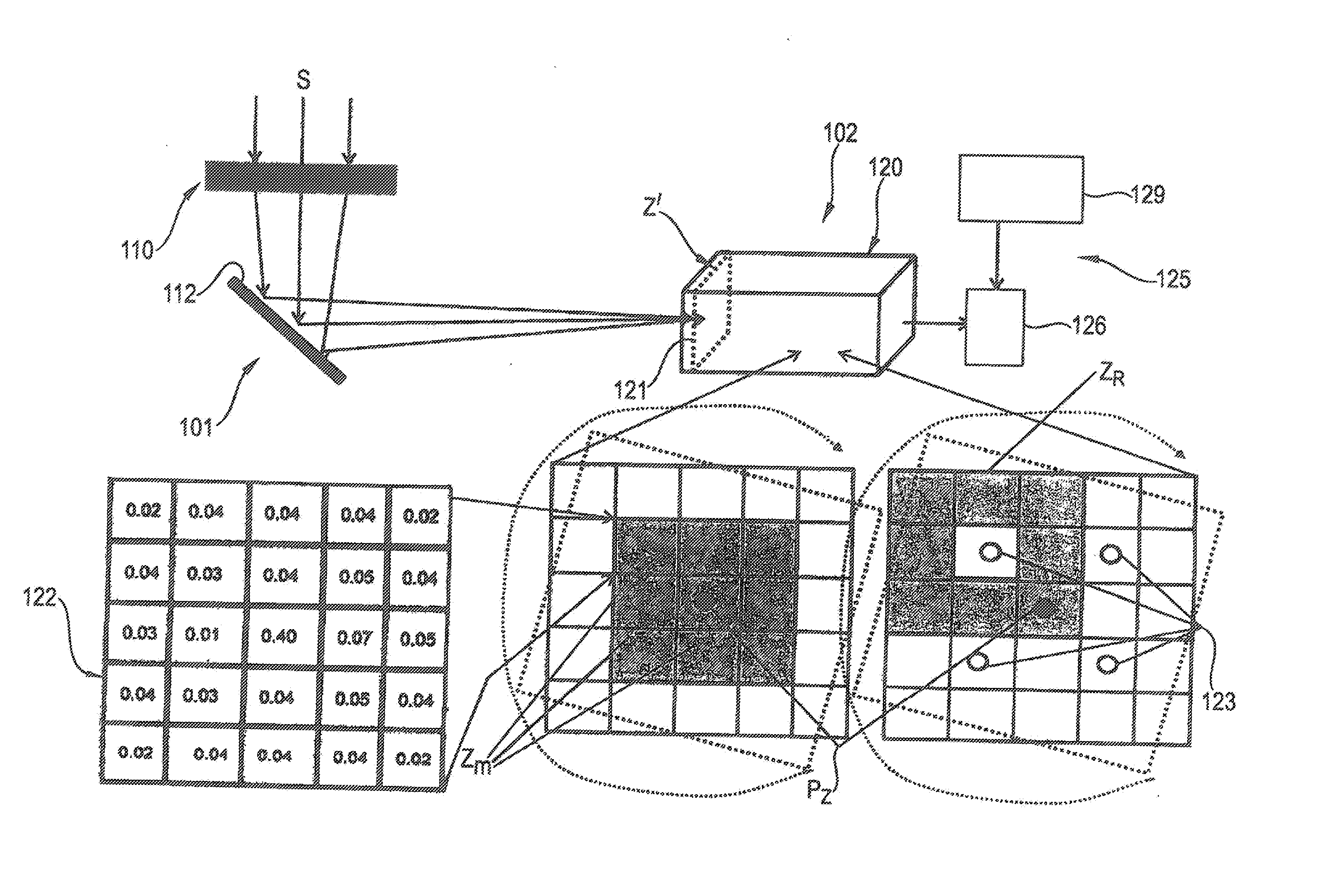
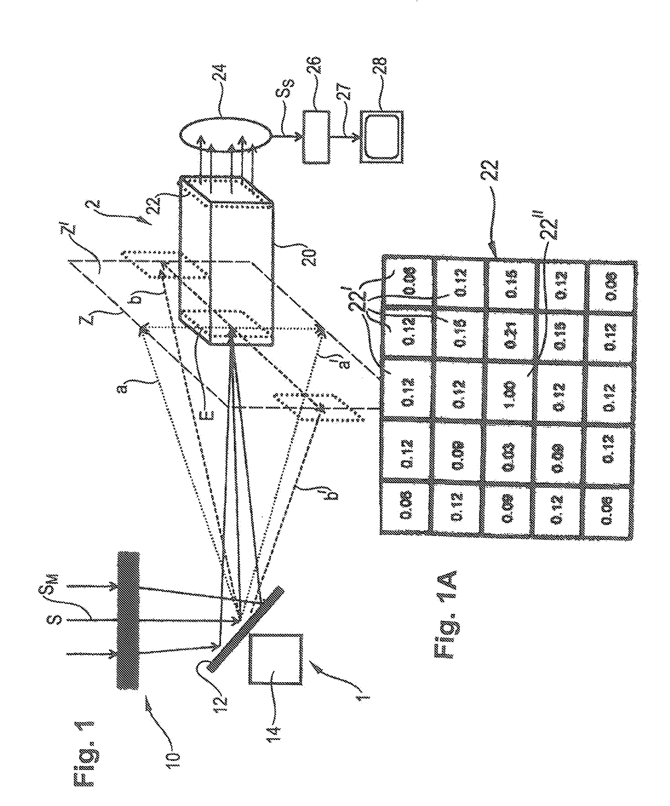
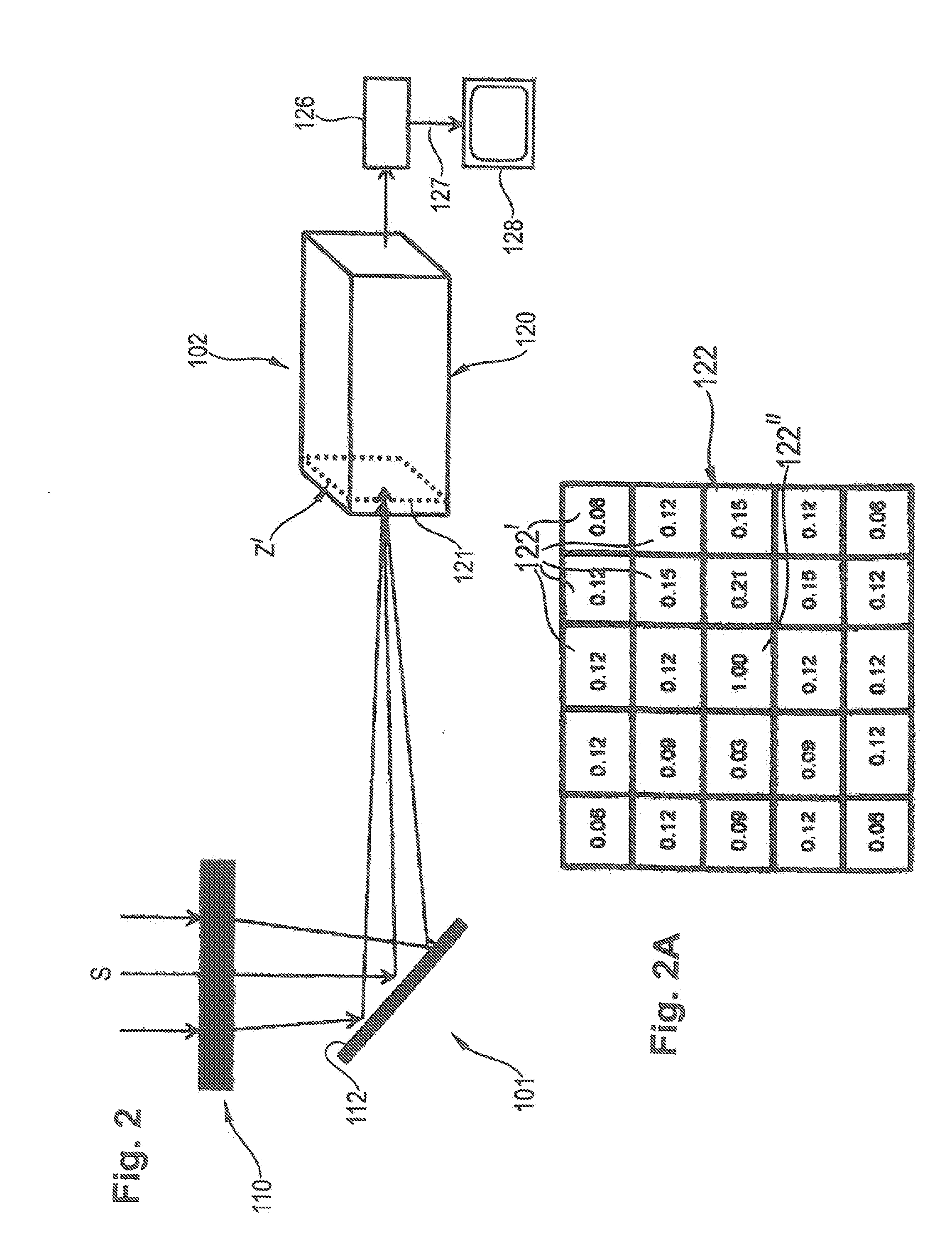
[0057]FIG. 1 shows an observation apparatus according to the invention, having an optical device 1 and an image processing device 2. The optical device 1 has a telescope unit 10 having a long-focus lens, which is shown only schematically in the figure. The telescope unit 10 captures electromagnetic radiation S of an observed scene in the visible spectrum of light and outside of the visible spectrum of light (for example infrared and / or ultraviolet radiation).

[0058]The radiation S captured by the telescope 10 is passed to a movable deflection mirror 12, which can be driven by a drive 14, shown only schematically in FIG. 1, to carry out a two-dimensional scanning movement. The vertical deflection of the deflection mirror 12 takes place in an angle range that is defined in FIG. 1, as an example, by the upper boundary line a of a center jet SM and by the lower boundary line a′, as well as by a first lateral boundary line b and a second lateral boundary line b′ of the center jet SM. In t...


PUM


Abstract

A method for image processing involves collecting image data of a scene as electromagnetic radiation and processing the image data to improve the signal-to-noise ratio of the image data. The image processing involves dividing a raw image that contains the image data into lines and columns, to create a raster image, superimposing a central raster filter element of a raster filter having an odd number of lines and an odd number of columns onto a raster image element, determining the brightness values of each of the raster image elements covered by the raster filter, wherein except for the central raster filter element, every other raster filter element has an individual light-reducing property, and adding up the brightness values to produce a total brightness value, and assigning this total brightness value to the raster image element covered by the central raster filter element. These image processing steps are repeated for all remaining raster image elements to produce a result image having the same resolution as the raw image from the total brightness values of the raster image elements.

Description

TECHNICAL FIELD[0001]Exemplary embodiments of the present invention relate to a method for image processing, a method for automatic object recognition, and observation apparatuses.BACKGROUND AND SUMMARY OF THE INVENTION[0002]In the field of remote observation of objects, particularly during the course of military reconnaissance, it is important to track moving objects, for example launched rockets having firing engines, over a great distance of up to 1500 km and to at first detect rockets that have stopped firing, with sufficient, if applicable artificial illumination, over a distance of up to 1000 km, to track them along their movement path, and to identify them. Even if optical observation apparatuses having long focal length lenses and high-resolution image sensors are used, it is not possible to obtain high-resolution images reproducing the engine jet flame object with sharp focus within the range of a few meters at an object distance of more than 500 km to as much as 1500 km, b...

Claims


Application Information

Patent Timeline
IPC IPC(8): H04N5/232G06K9/00G06T7/40G06T5/00G06T7/00G06V20/13
CPCH04N5/23229G06T5/002G06T7/004G06T2207/30212G06K9/00214G06T2207/10004G06T2200/28G06T7/408G06T5/20G06T2207/10036G06T7/70G06T7/90G06V20/13G06V10/243G06V10/255G06T5/70G06V20/653H04N23/80
Inventor PONGRATZ, HANS WOLFGANGHIEBL, MANFRED
Owner AIRBUS DEFENCE & SPACE
Learn More