Transducer amplification circuit

a technology of transducer and amplifier, applied in the direction of code conversion, instrument structure association, microphone structure association, etc., can solve problems such as severe constraints

Active Publication Date: 2015-10-01
ANALOG DEVICES INT UNLTD
View PDF5 Cites 56 Cited by
  • Summary
  • Abstract
  • Description
  • Claims
  • Application Information

AI Technical Summary

Benefits of technology

[0016]The signal coder of the transducer amplification circuit may comprise a frequency transposing circuit, such as a digital down-converter (DDC), which is configured to transpose or down-shift the ultrasonic frequency components of the second digital transducer signal to the audible frequency range. This feature allows the ultrasonic frequency components of the second digital transducer signal to be accurately represented or encoded in a data stream conforming to a standardized digital audio protocol, such as one of the protocols discussed above, using a relatively modest...

Problems solved by technology

The compact dimensions and battery source both put severe constraints to the maximum acceptable dimensio...

Method used


Image

  • Transducer amplification circuit
  • Transducer amplification circuit
  • Transducer amplification circuit

Examples


Embodiment Construction

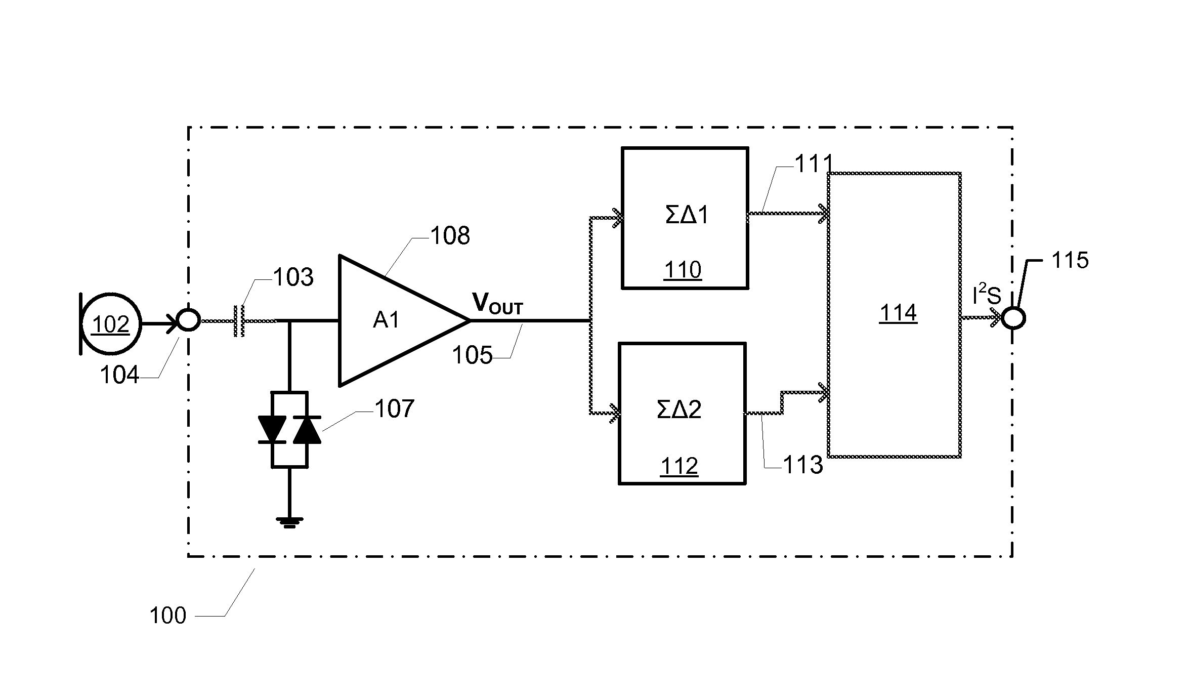
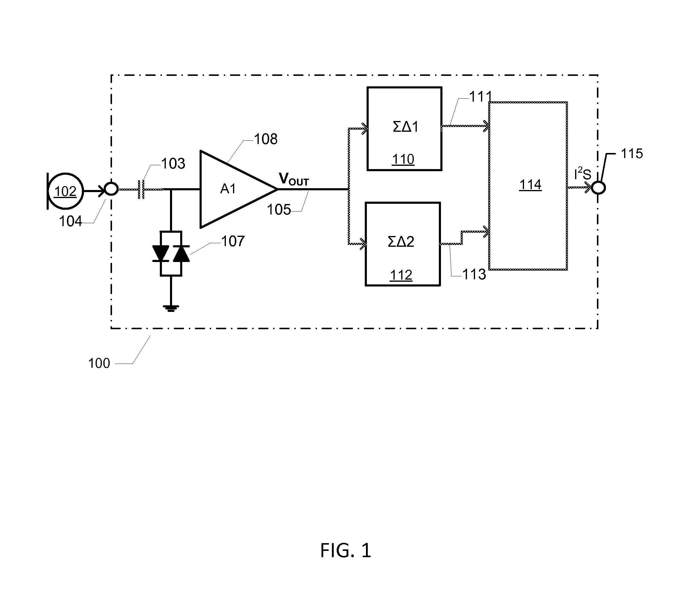
[0027]FIG. 1 is a schematic block diagram of a transducer amplification circuit 100 electrically connected to a MEMS microphone 102 via an input pad or terminal 104 of the circuit 100. The MEMS microphone has a frequency response that extends from the audible frequency range (20 Hz-20 kHz) to ultrasonic frequencies for example from 20 Hz to above 50 kHz such as to 100 KHz. The transducer amplification circuit 100 comprises a preamplifier A1 (108) with a preamplifier input coupled to the input terminal or pad 104 of the amplification circuit 100 through a DC blocking or ac coupling capacitor 103 for receipt of a microphone signal produced by the MEMS microphone 102. This microphone signal may comprise a mixture of audible frequency components and ultrasonic frequency components. The audible frequency components may comprise speech or music while the ultrasonic frequency components may origin from an ultrasonic sound emitter (not shown) for example mounted in a pen of the portable com...


PUM


Abstract

A transducer amplification circuit may include a preamplifier circuit with a signal input receiving a transducer signal to provide an amplified transducer signal comprising audible frequency components and ultrasonic frequency components. The transducer amplification circuit may include a first sigma-delta modulator configured to sample and quantize the amplified transducer signal to generate a first digital transducer signal comprising a first quantization noise signal. The first sigma-delta modulator may include a first noise transfer function having a high pass response in at least a portion of an audible frequency range to push the quantization noise signal to ultrasonic frequencies. A second sigma-delta modulator is configured to sample and quantize the amplified transducer signal to generate a second digital transducer signal comprising a second quantization noise signal. The second sigma-delta modulator may include a second noise transfer function with a magnitude minimum placed at the ultrasonic frequencies.

Description

FIELD OF THE INVENTION[0001]The present invention relates to a transducer amplification circuit comprising a preamplifier circuit which comprises a signal input for receipt of a transducer signal and is operable to provide an amplified transducer signal comprising audible frequency components and ultrasonic frequency components. The transducer amplification circuit also comprises a first sigma-delta modulator configured to sample and quantize the amplified transducer signal to generate a first digital transducer signal comprising a first quantization noise signal. The first sigma-delta modulator comprises a first noise transfer function (NTF) having a high pass response in at least a portion of an audible frequency range to push the quantization noise signal to ultrasonic frequencies. A second sigma-delta modulator is configured to sample and quantize the amplified transducer signal to generate a second digital transducer signal comprising a second quantization noise signal. The sec...

Claims


Application Information

Patent Timeline
IPC IPC(8): H04R3/00H03F1/32H03F3/38H03M3/00H03F3/181
CPCH04R3/00H03M3/356H03F2200/03H03F3/38H03F1/32H03F3/181G06F3/0433H04R1/04H04R19/005H04R19/04H04R2499/11
Inventor NGUYEN, KHIEM QUANGBERTHELSEN, KIM SPETZLERADAMS, ROBERT
Owner ANALOG DEVICES INT UNLTD
Why Eureka
Try Eureka