Fan control unit and power conditioner

Active Publication Date: 2015-10-08
SANSHA ELECTRIC MFG
View PDF13 Cites 18 Cited by
  • Summary
  • Abstract
  • Description
  • Claims
  • Application Information

AI Technical Summary

Benefits of technology

[0019]The present invention makes it possible to perform an effective cooling of a heat sink of which temperature rise is large thanks

Problems solved by technology

Since heat generated by the internal inverter or the like changes when the power generated varies, in a case where an air-cooling fan is kept turned on a

Method used


Image

  • Fan control unit and power conditioner
  • Fan control unit and power conditioner
  • Fan control unit and power conditioner

Examples


Embodiment Construction

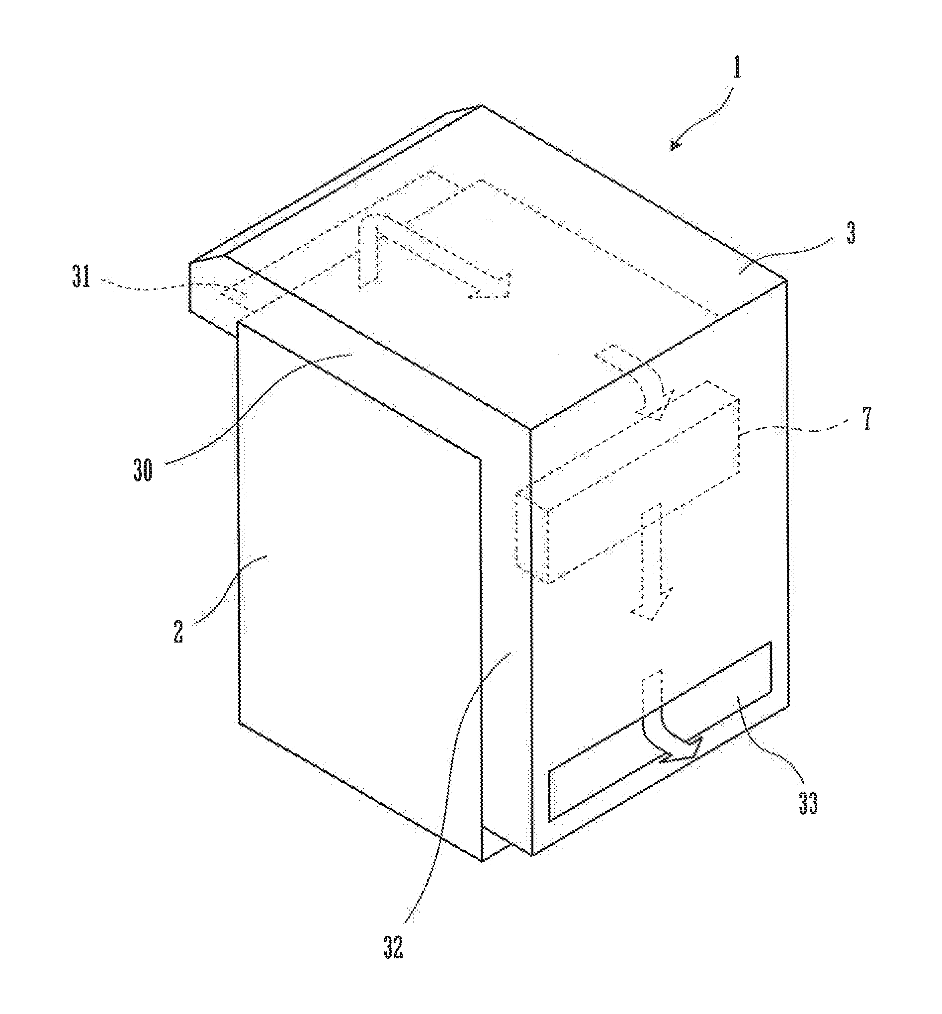
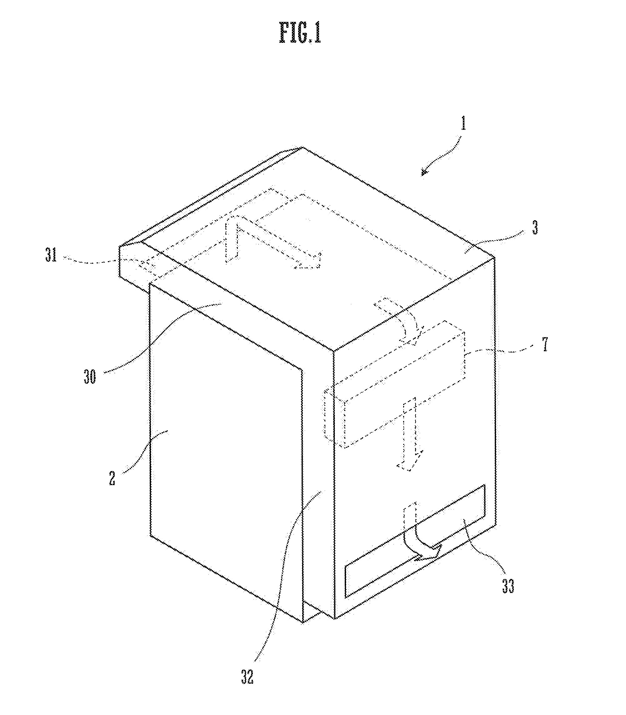
[0024]FIG. 1 is an external view of a power conditioner according to an embodiment of the present invention.

[0025]A power conditioner 1 is connected to a solar photovoltaic power generator which is not shown and to a commercial system power supply (system) in between, and has a function of outputting power generated by the solar photovoltaic power generator to the system. The power conditioner 1 includes: a main body section 2 provided with an inverter for converting DC power generated by the solar photovoltaic power generator into AC power and a control section for performing various controls; and a duct 3 that is provided in such a manner as to cover a top face and a rear face (right-side face in the Figure) of a casing of the main body section 2 entirely.

[0026]The duct 3 as a whole is L-shaped, and is provided with an air-intake port 31 of a slightly larger rectangular shape that opens, when viewed from the front, downward at an end portion located on the left side of a horizonta...


PUM


Abstract

A fan control unit includes: an internal fan that is provided inside a casing, in which an inverter containing a switching element is disposed, and generates an air current for air-cooling inside the casing; a heat sink which is exposed inside a duct provided on the casing and to which the switching element is attached, the duct being provided with an air-intake port and an air-exhaust port; an air-intake fan disposed at the air-intake port of the duct; an air-exhaust fan disposed at the air-exhaust port of the duct; and a control section performing a control such that the air-exhaust fan is turned on earlier than the air-intake fan and the internal fan as output power increases, and that the internal fan and the air-intake fan are turned off earlier than the air-exhaust fan as output power decreases from a state in which all the fans are kept turned on.

Description

TECHNICAL FIELD [0001]The present invention relates to a fan control unit that is applicable to inverters and the like, and to a power conditioner using the same.BACKGROUND ART [0002]In a power conditioner or the like that is disposed between a power generator such as solar photovoltaic power generator or the like and a system power supply (system), a fan control unit containing an air-cooling fan and a control section thereof is provided, together with an inverter. While in the power conditioner, DC power generated by the power generator is converted into AC power and then the AC power is outputted to the system, the power generated usually varies in time. In particular, in a case where the power generator is a solar photovoltaic power generator, the power generated changes considerably, depending on weather conditions and time of day. Since heat generated by the internal inverter or the like changes when the power generated varies, in a case where an air-cooling fan is kept turned...

Claims


Application Information

Patent Timeline
IPC IPC(8): F04D25/06F04D27/00F04D19/00
CPCF04D25/06F04D27/004F04D19/002F04D25/068F04D29/5813H02M7/003H05K7/206H05K7/20918Y02B30/70
Inventor TSUJIMOTO, KEISUKEMAKITANI, ATSUSHINISHIKAWA, KAZUHIROTAKAMORI, YUJI
Owner SANSHA ELECTRIC MFG
Why Eureka
Try Eureka