Device for monitoring inside of high-temperature furnace, and system for monitoring inside of high-temperature furnace provided with same

a technology for monitoring equipment and high-temperature furnaces, which is applied in the direction of instruments, furnaces, optical radiation measurement, etc., can solve the problems of difficult to observe the deposit accurately through the observation window, and the entire inside of the furnace looks red, so as to reduce the size and weight, the monitoring work can be suitably carried out, and the handling is good

Active Publication Date: 2015-10-08
MITSUBISHI HEAVY IND ENVIRONMENTAL & CHEM ENG CO LTD
View PDF2 Cites 16 Cited by
  • Summary
  • Abstract
  • Description
  • Claims
  • Application Information

AI Technical Summary

Benefits of technology

[0016]In the aforementioned device for monitoring the inside of the high-temperature furnace, as the partition members (barriers) are provided in the double pipe structure of the outer casing and the inner casing, one half of the space between the outer casing and the inner casing can be made into a first flow channel serving as a feed flow channel (main channel) of cooling water, and the other half can be made into a second flow channel serving as a return flow channel (return channel) of the cooling water. Thereby, in comparison with a related art device constructed in a triple or quadruple pipe structure, the device can be remarkably reduced in size and weight.
[0017]Thus, according to the aforementioned device for monitoring the inside of the high-temperature furnace, in comparison with the related art, the device has good handleability. When the inside of the furnace is monitored as needed, no great burden occurs even if the device is inserted into and installed in the furnace each time. Without a limitation on the number of times of monitoring the inside of the furnace, the monitoring work can be suitably carried out. Further, even when the observation window used when the device is inserted into the furnace is blocked by the slag or the clinker, the device is miniaturized, and thus work of removing the slag or the clinker can be remarkably reduced compared to the related art.
[0018]Further, in the aforementioned device for monitoring the inside of the high-temperature furnace, the outer casing and the inner casing are detachably connected via the waterproof plugs, and thereby the double pipe structure can be constructed. For this reason, as the waterproof plugs are removed, the inner casing can be removed from the outer casing. Thereby, exchange or maintenance of the imaging device such as a CCD camera or a fiberscope, adjustment of the imaging device in a field-of-view direction, etc. can be easily performed. Accordingly, it is possible to improve the handleability of the device for monitoring the inside of the high-temperature furnace, and to monitor the inside of the high-temperature furnace in a more accurate and efficient way.
[0019]Furthermore, in the aforementioned device for monitoring the inside of the high-temperature furnace, since the gate is formed in the inner casing and is closed by the detachable cover member, the cover member is removed as needed, and the exchange or maintenance of the imaging device, the adjustment of the imaging device in the field-of-view direction, etc. can be more easily performed through the gate.
[0020]Further, in the aforementioned device for monitoring the inside of the high-temperature furnace, the plurality of imaging devices are provided in the inner casing, and the partial image capturing regions of the neighboring imaging device are arranged to overlap, that is, the imaging devices are arranged in order to obtain a stereoscopic image. Thereby, it is possible to acquire a 3D image of the deposit whose image is captured at the portion at which the image capturing regions overlap. Thereby, a distance between the deposit and the imaging devices can be accurately measured in the high-temperature furnace. As a result, the size of the deposit can be discriminated precisely. Accordingly, it is possible to drive the auxiliary burner with a suitable timing corresponding to the size of the deposit and to release the deposit. It is possible to eliminate decision of the output of the auxiliary burner depending on experience and intuition of a worker as in the related art, or stopping of the operation of the furnace to release the deposit with manpower when the deposit grows too large.
[0021]In the aforementioned system for monitoring the inside of the high-temperature furnace, operation and effects of the device for monitoring the inside of the high-temperature furnace can be obtained, and the controller discriminates the size of the deposit from the image acquired by the imaging devices of the device for monitoring the inside of the high-temperature furnace, and controls driving of the auxiliary burner and the burning / melting target feeder based on the size of the deposit. Thereby, it is possible to discriminate the growth of the deposit to automatically perform optimal operation control of the auxiliary burner. It is possible to reduce a fuel cost, and to prevent damage to the furnace. Further, the driving of the burning / melting target feeder is controlled such that an amount of charge (feed) of the burning / melting target is reduced depending on an amount of output of the auxiliary burner. Thereby, when the auxiliary burner is ignited, an amount of treatment of the burning / melting target can be automatically reduced to lighten the load of the furnace.

Problems solved by technology

However, the entire inside of the furnace looks red due to high-temperature incinerated molten materials, and it is difficult to observe the deposit accurately through the observation window.

Method used


Image

  • Device for monitoring inside of high-temperature furnace, and system for monitoring inside of high-temperature furnace provided with same
  • Device for monitoring inside of high-temperature furnace, and system for monitoring inside of high-temperature furnace provided with same
  • Device for monitoring inside of high-temperature furnace, and system for monitoring inside of high-temperature furnace provided with same

Examples


Embodiment Construction

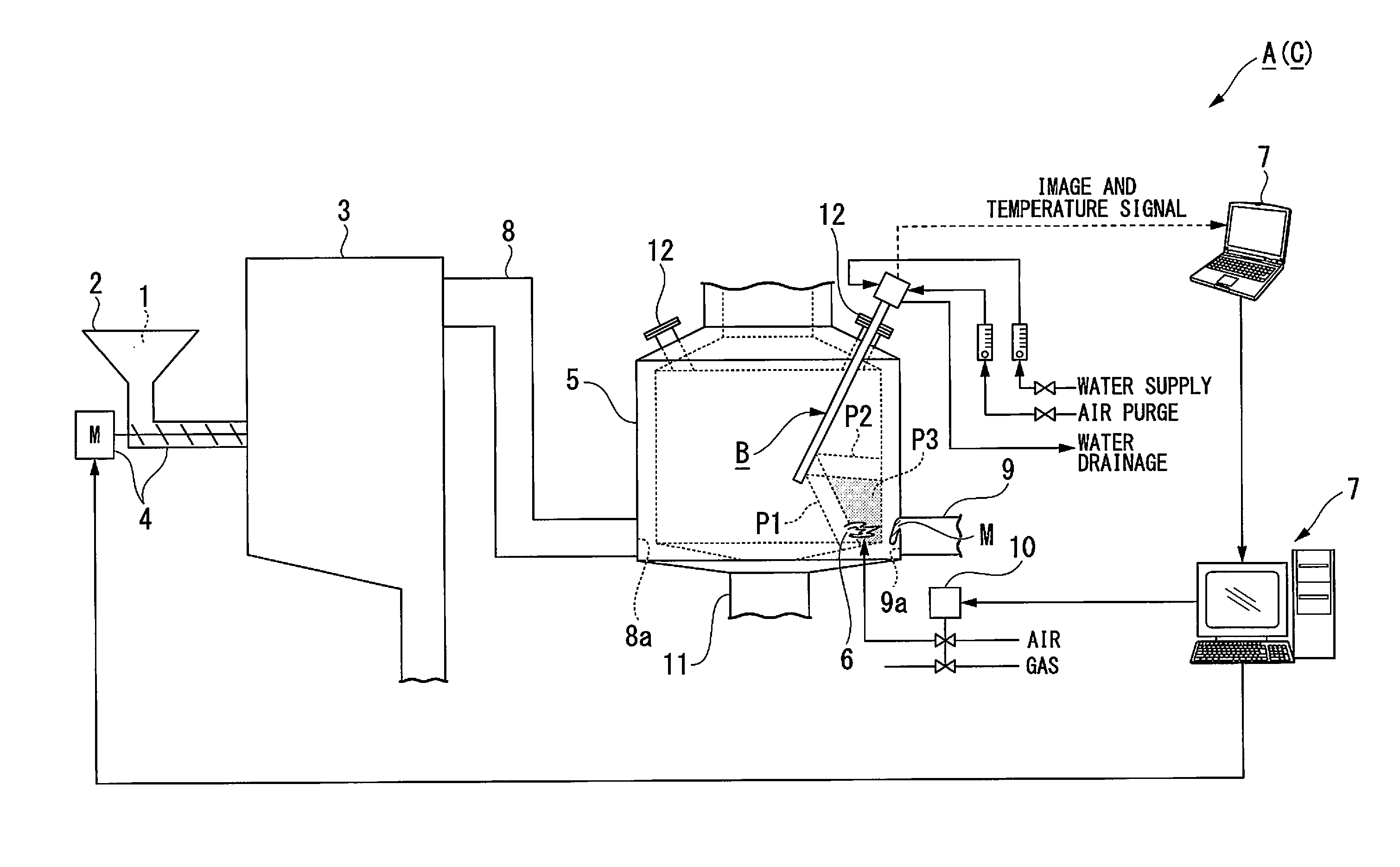
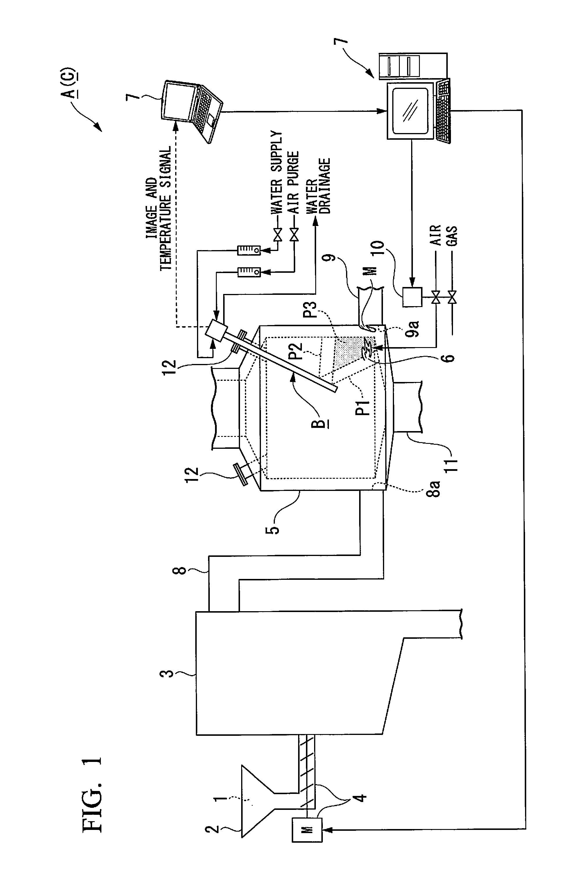
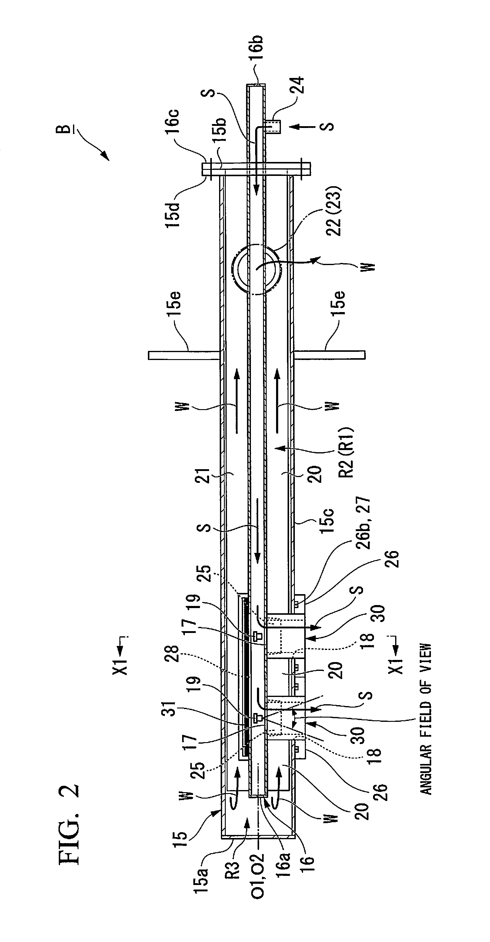
[0033]Hereinafter, a device for monitoring the inside of a high-temperature furnace and a system for monitoring the inside of a high-temperature furnace provided with the same according to an embodiment of the present invention will be described with reference to FIGS. 1 to 10. Further, it is described in the present embodiment that the device for monitoring the inside of the high-temperature furnace and the system for monitoring the inside of the high-temperature furnace are provided for a facility that performs gasification melting treatment on an incinerating target (burning / melting target) such as urban refuse. Of course, the device for monitoring the inside of the high-temperature furnace and the system for monitoring the inside of the high-temperature furnace according to the present embodiment may be applied to other furnaces such as an ash melting furnace in which much floating slag and soot are generated, and may be adequately used, for instance, for a furnace with an inter...


PUM

PropertyMeasurementUnit
temperatureaaaaaaaaaa
diameteraaaaaaaaaa

Abstract

Provided is an outer casing having a bottomed tube shape, the casing having a cooling water supply port, and a cooling water discharge port, and being inserted into a high-temperature furnace; an inner casing having a bottomed tube shape inserted into the outer casing; an imaging unit that is disposed in the inner casing which captures an image of the exterior of the outer casing; and partition members that are between an inner surface of the outer casing and an outer surface of the inner casing which define a first flow channel, a second flow channel, and a communicating channel for communicating the first flow channel and the second flow channel between the bottom of the outer casing and the partition members.

Description

TECHNICAL FIELD[0001]The present invention relates to a device for monitoring the inside of a high-temperature furnace, and a system for monitoring the inside of the high-temperature furnace provided with the same.[0002]Priority is claimed on Japanese Patent Application No. 2012-234943, filed on Oct. 24, 2012, the content of which is incorporated herein by reference.BACKGROUND ART[0003]As floating slag and soot are generated in a high-temperature furnace such as a gasification melting furnace, an ash melting furnace, or a refuse incinerator, clinker or slag (deposit) may be deposited and grow. For example, as illustrated in FIG. 11, due to the deposition and growth of the clinker or slag, a gas stream is obstructed and poor melting of fly ash occurs, or work of releasing the deposit by raising output of an auxiliary burner is required in the early stage of the deposition, or when the deposition and growth thereof are advanced to some extent, an operation is stopped and work of relea...

Claims


Application Information

Patent Timeline
Patent Type & Authority Applications(United States)
IPC IPC(8): F27D21/02H04N5/225
CPCF27D21/02F27D2021/026H04N2005/2255H04N5/225F23M11/04C10J3/00G01J5/0893G01J5/0044G01J5/04G01J5/061G01J2005/0077C21C2005/5288F27D21/0014C10J3/46F27D21/00C10J3/723Y02P10/20G01J5/051H04N23/00H04N23/555
Inventor NAGAI, HIROSHIHARADA, TOMOHIRONOMA, AKIRASHIRAI, TOSHIMASA
Owner MITSUBISHI HEAVY IND ENVIRONMENTAL & CHEM ENG CO LTD
Why Eureka
Try Eureka