
Controller executing sequential program using multi-core processor

a multi-core processor and sequential program technology, applied in the field of controllers, can solve the problems of increasing processing time, affecting the performance of sequential programs, and putting pressure on the processing time of other processes

Inactive Publication Date: 2015-10-08
FANUC LTD
View PDF7 Cites 8 Cited by
  • Summary
  • Abstract
  • Description
  • Claims
  • Application Information

AI Technical Summary

Benefits of technology

The present invention provides a controller that can execute a sequential program using a multi-core processor without causing a cache miss. This means that even if the program is too big to fit in the cache, the controller can still execute it quickly and efficiently. This results in faster machine tools and improved performance.

Problems solved by technology

The processing time for the sequential program significantly affects the performance of the numerical controller.
An increased number of steps in the sequential program resulting from additional functions of the numerical controller tend to also increase the processing time.
The extended processing time for the sequential program puts pressure on the processing time for other processes.
Furthermore, given that the sequential program fails to complete processing within the predetermined time, the numerical controller does not function properly as a system that controls the machine tool.
However, in recent years, the operating frequency of processors has leveled off due to the problem of an increase in power consumption and in the amount of heat generation.
On the other hand, in executing a sequential program, for which the use of threads is difficult, the multi-core processor poses the problem of increased cache misses as described below.
Thus, compared to a single-core processor with the same capacity of cache memories, the multi-core processor is likely to cause cache misses in executing the sequential program.
Moreover, when a large-sized sequential process that exceeds the capacity of a first-level instruction cache memory is executed, the program fails to be entirely stored into the instruction cache memory.
Prefetching improves a cache hit rate but has difficulty in eliminating cache misses.
For example, dynamic conditional branching may lead to a cache miss resulting from a failure in speculative prefetching.
Furthermore, a memory read speed is low compared to the operating frequency of the processor, and thus, prefetching may fail to be performed in time, resulting in memory read wait.

Method used


Image

  • Controller executing sequential program using multi-core processor
  • Controller executing sequential program using multi-core processor
  • Controller executing sequential program using multi-core processor

Examples


first embodiment

[0047]First, the controller according to the present invention will be described using FIGS. 2 to 11.

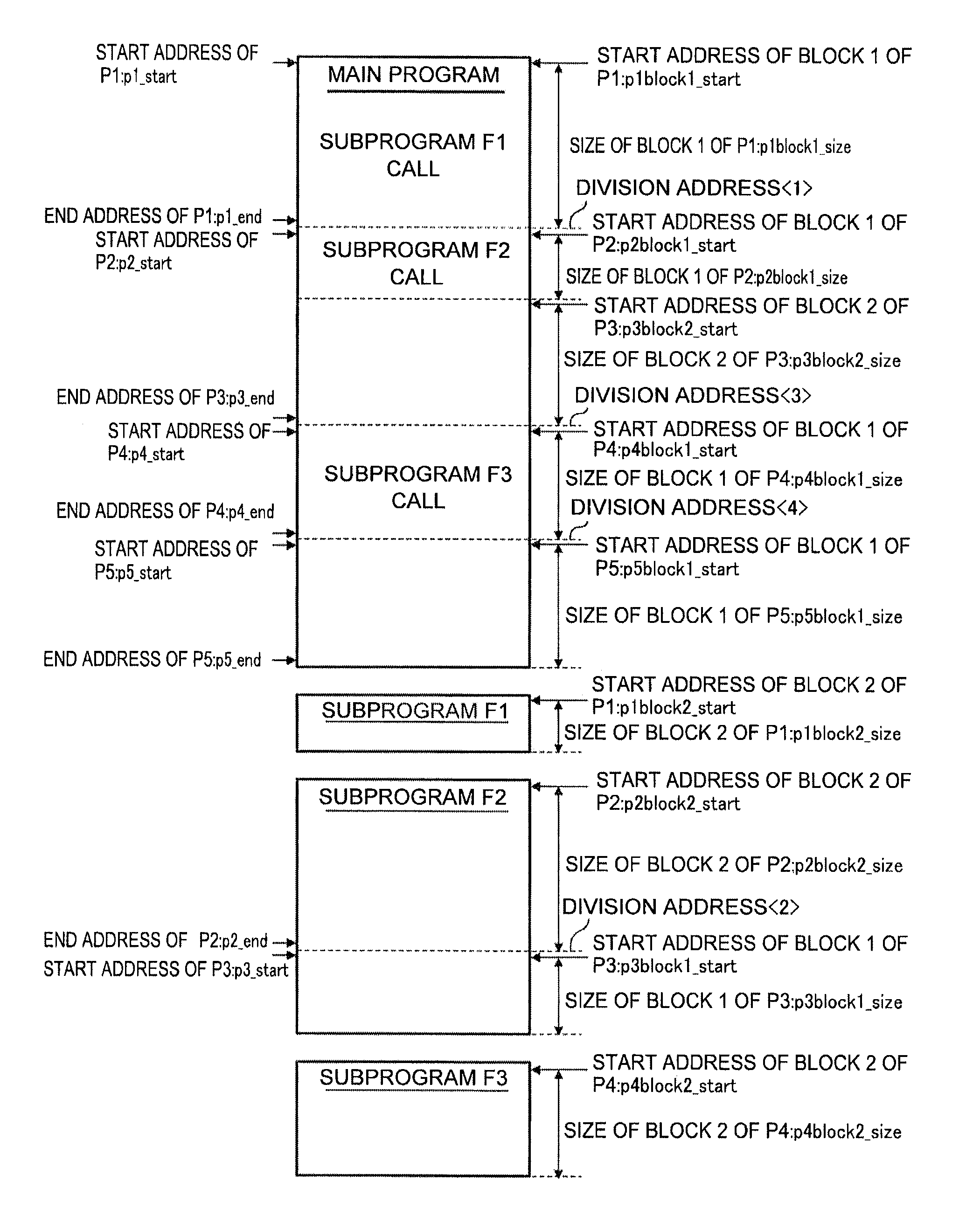
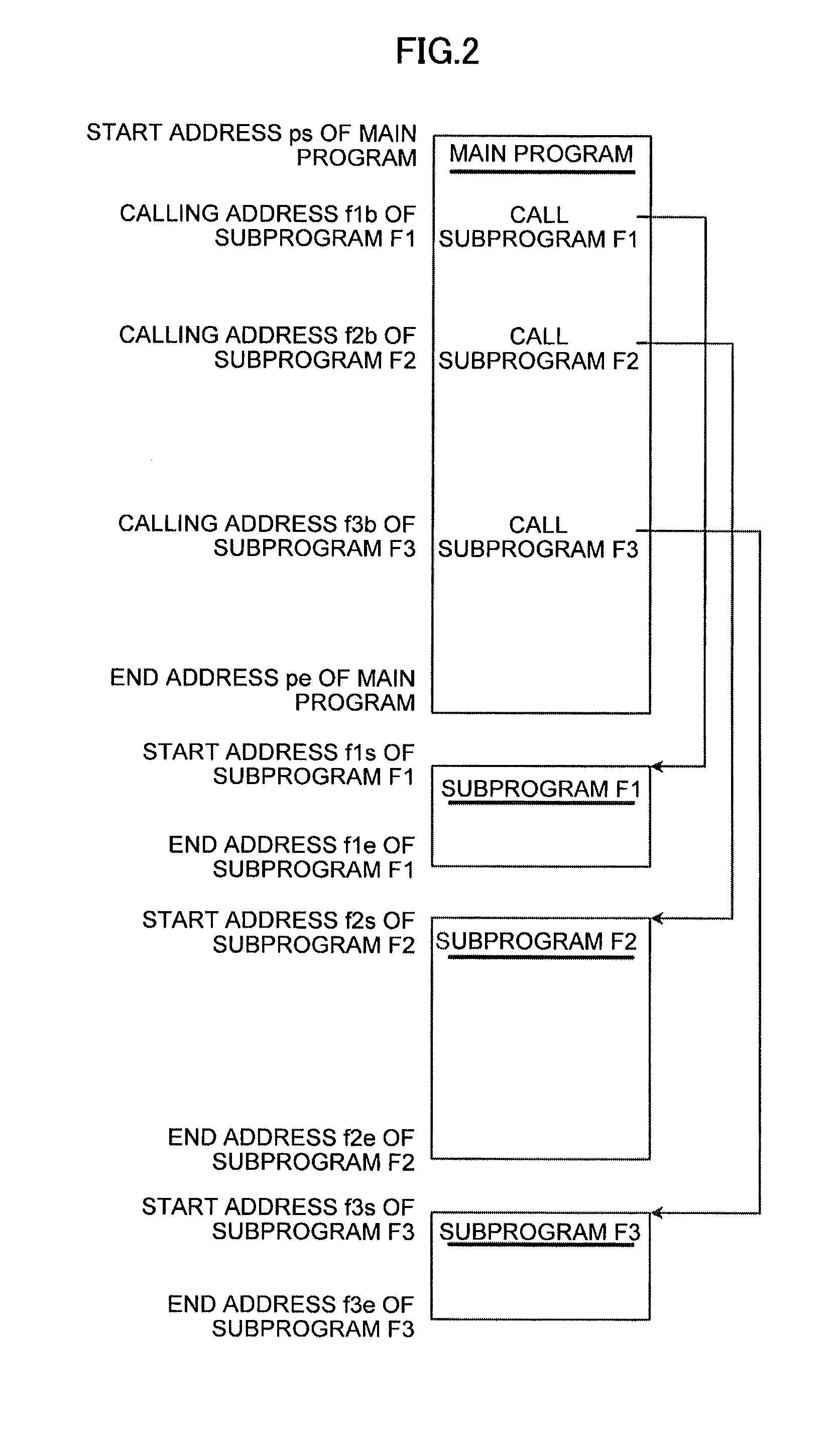
[0048]FIG. 2 is a diagram depicting arrangement of the sequential program P on the memory (for example, the DRAM 79). FIG. 3 is a flowchart depicting processing by a program profile information generating section in the first embodiment of the controller according to the present invention. FIG. 4 is a diagram depicting an example of program profile information.

[0049]As depicted in FIG. 2, in the sequential program P, the start address of a main program is denoted by ps, and the end address of the main program is denoted by pe. A subprogram F1 is called up using an address f1b. A subprogram F2 is called up using an address f2b. A subprogram F3 is called up using an address f3b. The start address of the subprogram F1 is denoted by f1s, and the end address of the subprogram F1 is denoted by f1e. The start address of the subprogram F2 is denoted by f2s, and the end address of the subprog...

second embodiment

[0118]the controller according to the present invention will be described with reference to FIGS. 12 to 15.

[0119]FIG. 12 is a flowchart depicting processing by a processing time estimating section and a cache storage time estimating section in a second embodiment of the controller according to the present invention. FIG. 13 is a diagram depicting an example of the program execution information. FIG. 14 is a flowchart depicting processing by a scheduler section in the second embodiment of the controller according to the present invention. FIG. 15 is a diagram depicting a sequence executed by the second embodiment of the controller according to the present invention. In FIG. 15, the instruction cache memory is simply referred to as the “cache”.

[0120]The controller of the present embodiment corresponds to the controller of the above-described first embodiment in which additionally the processing time estimating section analyzes the program data on the memory to estimate the processing ...


PUM


Abstract

A sequential program is divided into programs each with a size fitted into a cache memory using program profile information and prepared cache memory information. Program profile information on the sequential program and information on the cache memory are acquired. Based on the acquired information, division addresses at which the sequential program is divided are determined. The IDs of the division programs, assigned core numbers, the start addresses and end addresses of the programs, and cache storage block information are stored in a memory as program execution information.

Description

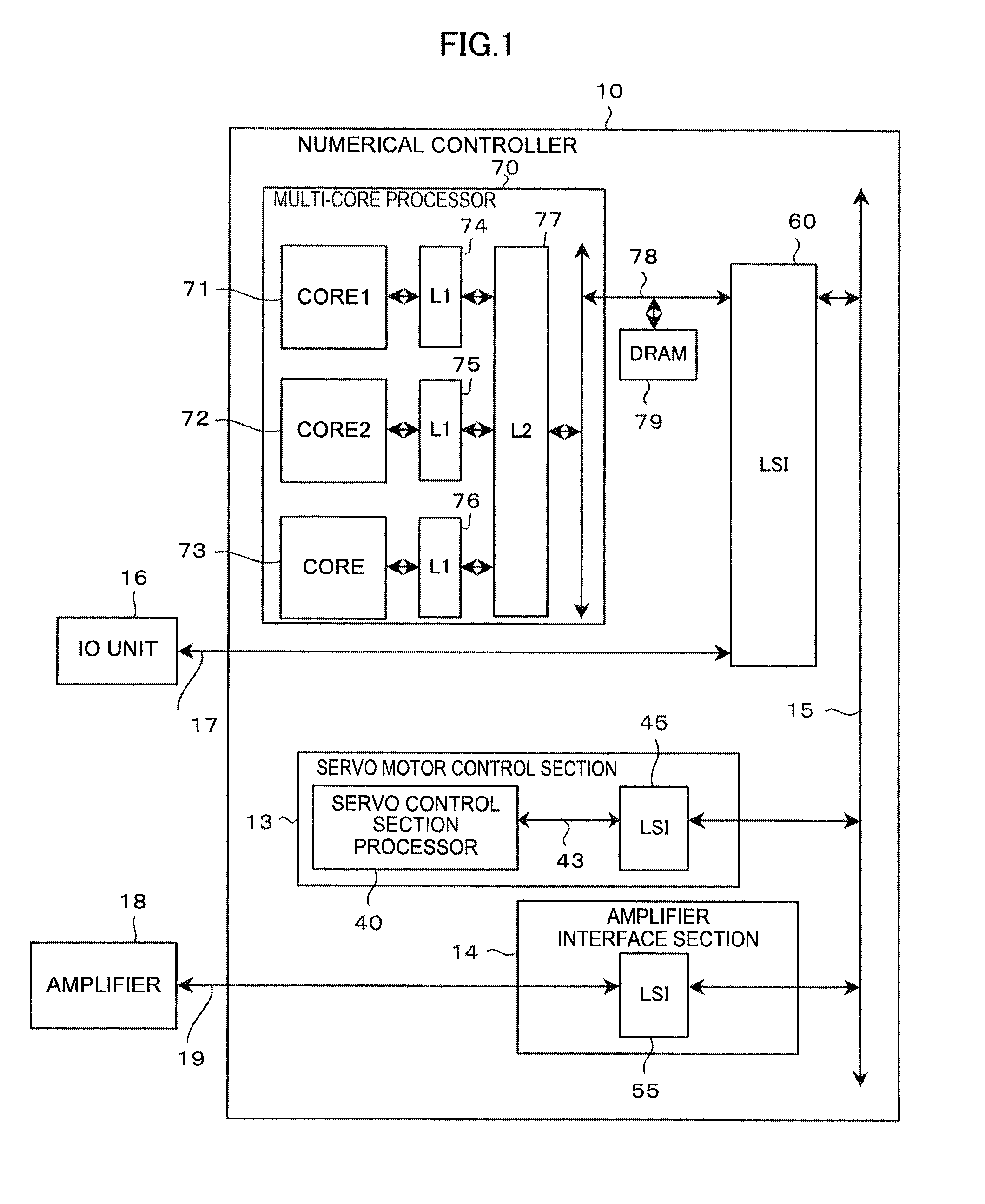
BACKGROUND OF THE INVENTION[0001]1. Field of the Invention[0002]The present invention relates to a controller that controls a machine tool, and in particular, to a controller that executes a sequential program using a multi-core processor.[0003]2. Description of the Related Art[0004]FIG. 16 is a diagram depicting a conventional numerical controller that executes a sequential program using a multi-core processor.[0005]The numerical controller 10 includes a numerical control section 11, a PMC section 12, a servo motor control section 13, and an amplifier interface section 14. The numerical control section 11 includes a processor core 20, a first-level cache memory (L1 cache) 21, a second-level cache memory (L2 cache) 22, a DRAM 24, and a peripheral LSI 25. These elements are connected together via a bus 23. The PMC section 12 includes a processor core 30, a first-level cache memory (L1 cache) 31, a second-level cache memory (L2 cache) 32, a DRAM 34, and a peripheral LSI 35. These elem...

Claims


Application Information

Patent Timeline
IPC IPC(8): G06F12/08G06F9/30
CPCG06F12/0875G06F2212/452G06F9/30145G05B19/04G06F12/0811G06F9/445G06F9/5066G06F2209/5017G06F2209/507G06F9/3814G06F9/3802
Inventor ENDOU, KATSUHIRO
Owner FANUC LTD
Learn More