
System and Method for High Concentration Nitric Oxide Delivery

a nitric oxide and high concentration technology, applied in the field of high concentration nitric oxide delivery, can solve the problems of long contact period between no and oxygen in such systems, more than a second, and increased risk of nosub>2 /sub

Inactive Publication Date: 2015-10-15
12TH MAN TECH
View PDF4 Cites 4 Cited by
  • Summary
  • Abstract
  • Description
  • Claims
  • Application Information

AI Technical Summary

Benefits of technology

The present invention is about a system and method for delivering a high therapeutic concentration of nitric oxide gas to a patient while minimizing the formation of nitrogen dioxide and the need for adding supplemental oxygen. The system includes a gas mixing device and a gas mixing swirl plate that are designed to keep the contact period between nitric oxide and oxygen as short as possible, reducing the risk of toxic effects. The method involves injecting nitric oxide gas into the ventilator circuit in a way that maintains the concentration of nitric oxide in the inhaled gas at a safe level. The technical effects of the invention include improved safety and more effective therapeutic applications of nitric oxide gas.

Problems solved by technology

However, there can be a long, more than a second, contact period between NO and oxygen in such systems because the NO gas is often injected into the ventilator circuit a substantial distance, perhaps up to six feet, upstream from the point where it enters the patient's lungs.
A long contact period can be problematic because NO and oxygen react to form nitrogen dioxide (NO2), which is highly toxic and must be kept below about 3-5 ppm in the air inhaled by the patient.
However, the addition of supplemental oxygen is undesirable because it requires additional equipment, including an oxygen source, and increases the risk of NO2 formation because higher oxygen concentrations increases the reaction rate between NO and oxygen.

Method used


Image

  • System and Method for High Concentration Nitric Oxide Delivery
  • System and Method for High Concentration Nitric Oxide Delivery
  • System and Method for High Concentration Nitric Oxide Delivery

Examples


experimental examples

[0045]The invention is further described in detail by reference to the following experimental examples. These examples are provided for purposes of illustration only, and are not intended to be limiting unless otherwise specified. Thus, the invention should in no way be construed as being limited to the following examples, but rather, should be construed to encompass any and all variations which become evident as a result of the teaching provided herein.

[0046]Without further description, it is believed that one of ordinary skill in the art can, using the preceding description and the following illustrative examples, make and utilize the present invention and practice the claimed methods. The following working examples therefore, specifically point out exemplary embodiments of the present invention, and are not to be construed as limiting in any way the remainder of the disclosure.

example 1

Nitric Oxide Delivery at 160 ppm Using 5,000 ppm NO Source

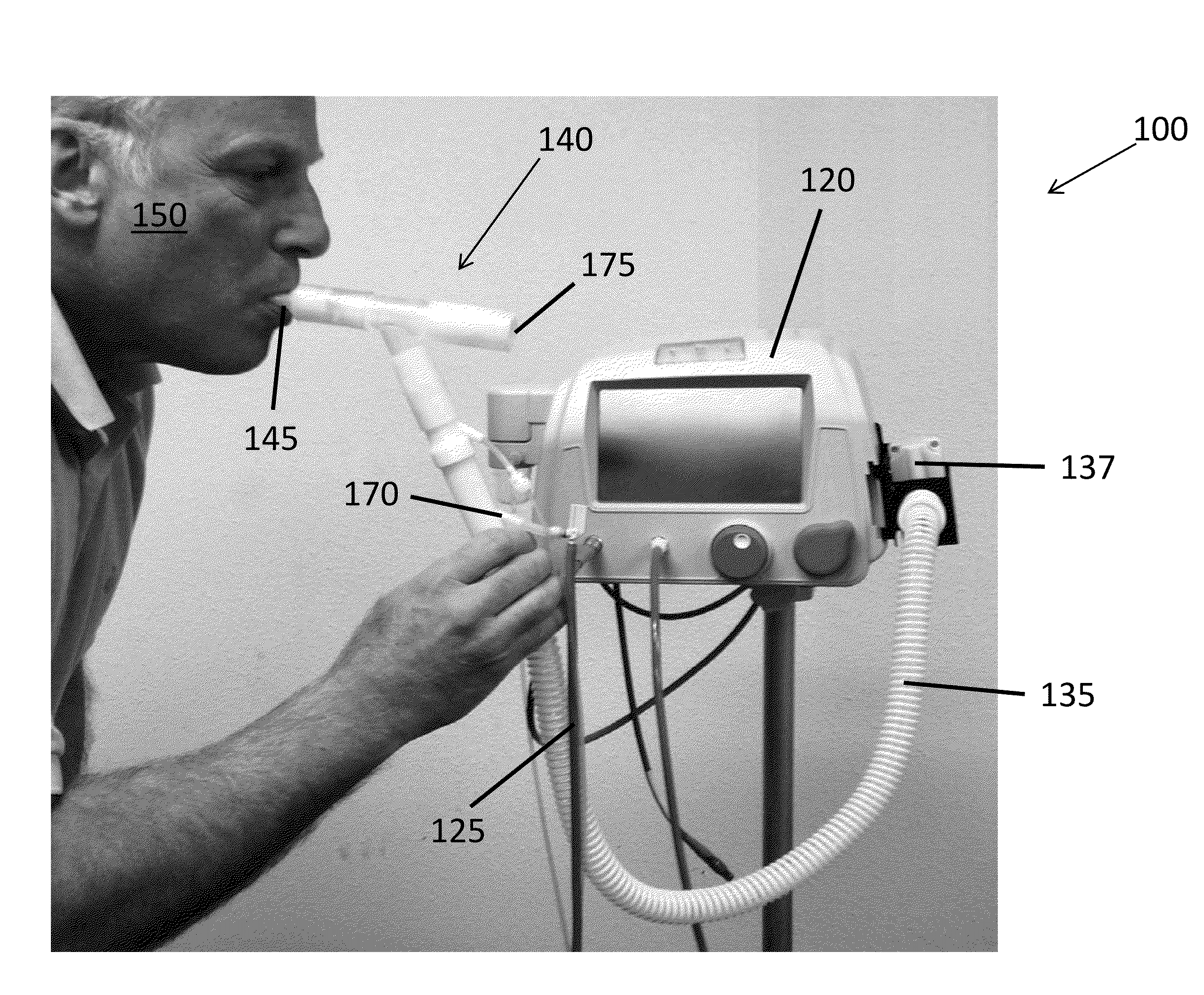
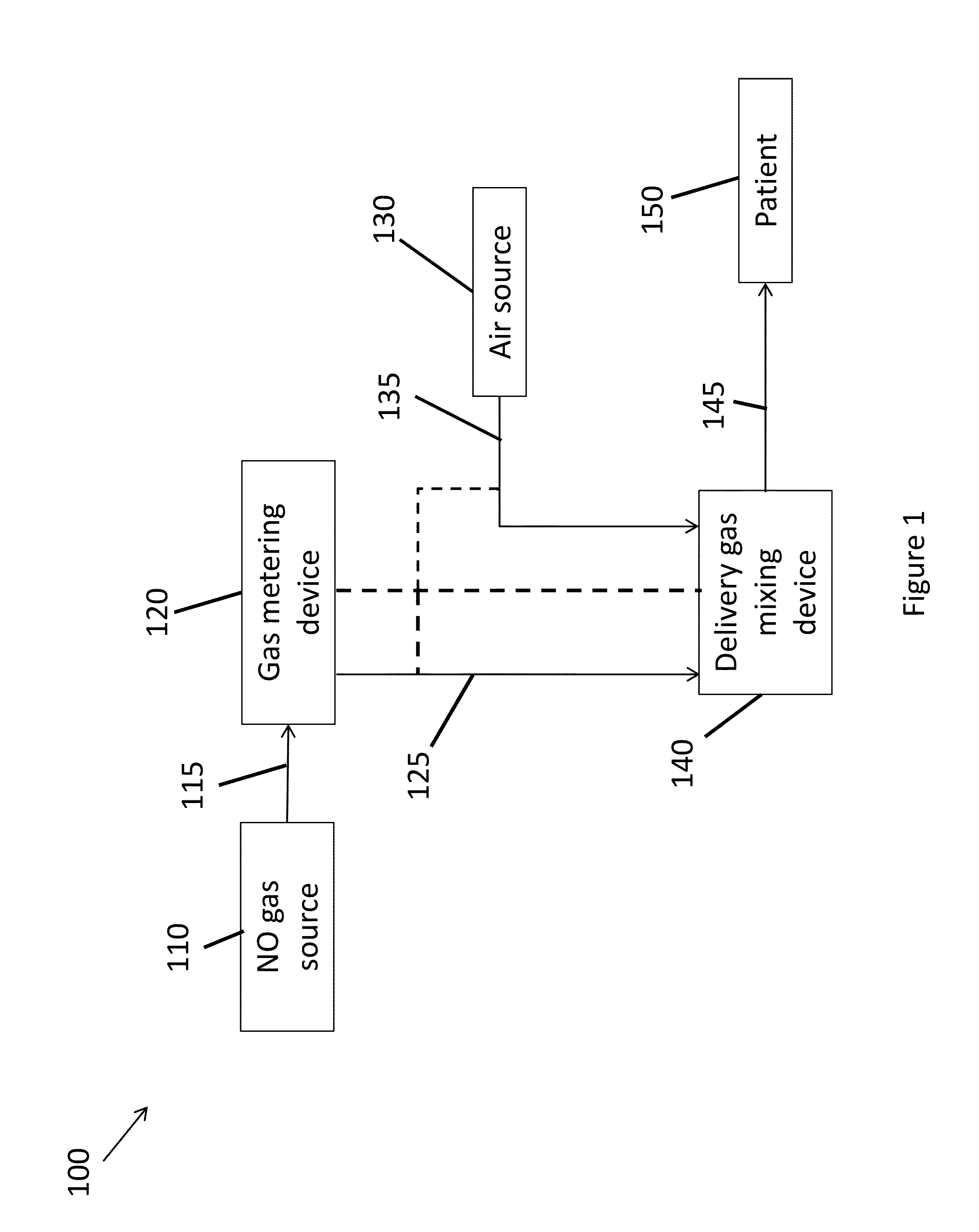
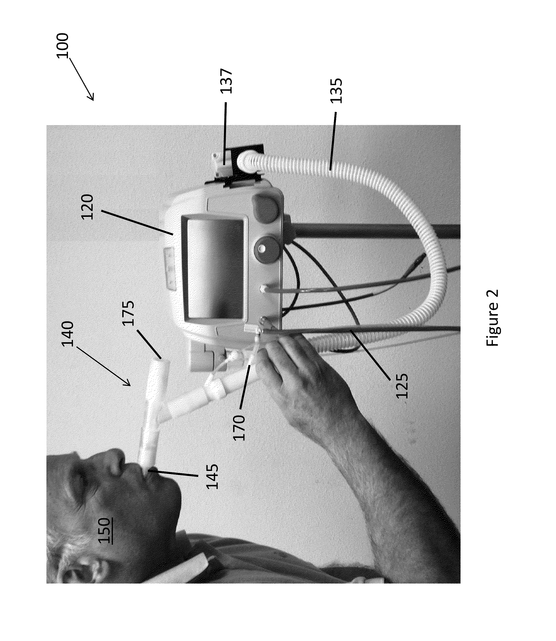
[0047]A stock cylinder containing 5000 ppm nitric oxide gas (Praxair, Connecticut) with the balance being nitrogen gas was connected to a dynamic gas metering system (12th Man Technologies, California) that was programmed to deliver a fixed concentration of 160±16 ppm NO. The metering system was connected to the gas mixing and administration device 140 as described in FIG. 2 and outlet 145 was connected to a mechanical test lung (Michigan Instruments, Michigan) that was configured to spontaneously breathe. A calibrated electronic flow sensor (TSI, Minnesota) was placed in-line with the metering system flow sensor and the output was connected to a computerized digital data collection system (LabView, National Instruments, Texas). The metering system contained sensors for monitoring inhaled NO, NO2 and oxygen. Once the test lung started breathing simulation, continuous recording of the flow pattern, and measurement of the inhal...


PUM


Abstract

The present invention relates to systems and methods for administering high concentrations of nitric oxide (NO) gas to a patient without the need to provide supplemental oxygen to the patient. The systems and methods can be used to administer high therapeutic amounts of NO gas, for example a gas comprising 160 ppm NO, while forming little or no residual nitrogen dioxide (NO2). The method is based on using a NO gas source with a relatively high NO concentration, for example 5,000 ppm, while rapidly mixing the gas from the NO gas source with air immediately prior to administering the gas to a patient.

Description

CROSS-REFERENCE TO RELATED APPLICATIONS[0001]This application claims priority to U.S. Patent Application Ser. No. 61 / 977,448, filed Apr. 9, 2014, the entire contents of which are incorporated herein by reference.BACKGROUND OF THE INVENTION[0002]The administration of nitric oxide (NO) gas can be used for various therapeutic applications. For example, NO is currently approved for use in the U.S. to treat pulmonary hypertension in newborns. Typically, NO is delivered to patients while they are on mechanical ventilators, and the NO is injected into the breathing circuit before the inspired gas enters the humidifier of the ventilator. Systems for injecting NO typically monitor the patient's dynamic inspiratory flow, and inject NO proportionally to the inspired flow to keep the concentration of NO in the inhaled gas constant (see, e.g., Bathe et al., U.S. Pat. No. 5,558,083 and Bathe et al., U.S. Pat. No. 6,125,846, the contents of both of which are incorporated by reference in their enti...

Claims


Application Information

Patent Timeline
Patent Type & Authority Applications(United States)
IPC IPC(8): A61M16/12A61K33/00A61M16/06A61K9/00
CPCA61M16/12A61M16/06A61K33/00A61K9/007A61M16/208A61M2016/0039A61M2016/1025A61M2016/1035A61M2202/0275A61M2205/3569A61M2205/3592A61M15/0021A61M16/085A61M16/125
Inventor STENZLER, ALEXMILLER, CHRISTOPHER C.HAN, STEVE
Owner 12TH MAN TECH
Learn More