Refrigeration cycle device

a technology of refrigerating cycle and refrigeration components, which is applied in the direction of refrigeration components, transportation and packaging, light and heating equipment, etc., can solve the problems of increasing the occupied space of the vehicle, increasing the cost due to the increase in the risk of lowering so as to reduce the number of components, improve the cooling performance and heating performance, and reduce the occupied space

Active Publication Date: 2015-10-15
DENSO CORP +1
View PDF12 Cites 9 Cited by
  • Summary
  • Abstract
  • Description
  • Claims
  • Application Information

AI Technical Summary

Benefits of technology

[0017]In view of such points, it is an objective of the present disclosure to reduce an occupied space within a vehicle, reduce the number of components, improve a cooling performance and a heating performance, reduce a sealed amount of refrigerant and refrigerant oil, and reduce a refrigerant leakage, in a refrigeration cycle device that enlarges a temperature adjustment range of the blown out air into the space to be air-conditioned during the dehumidification operation.
[0018]According to an aspect of the present disclosure, a refrigeration cycle device is used for an air-conditioning apparatus that performs a dehumidification operation in which an air blown to a space to be air-conditioned is cooled and dehumidified and the dehumidified blown air is heated. The refrigeration cycle device includes a compressor that compresses and discharges a refrigerant, a radiator in which the refrigerant discharged from the compressor radiates a heat, an outside heat exchanger in which the refrigerant flowing out of the radiator exchanges heat with an outside air, an evaporator in which the refrigerant flowing out of the outside heat exchanger is evaporated via heat exchange between the refrigerant flowing out of the outside heat exchanger and the blown air before passing through the radiator, a first refrigerant passage guiding the refrigerant flowing out of the radiator to an inlet side of the outside heat exchanger, a first throttling device having two refrigerant ports to or from which the refrigerant flows in or out, the first throttling device being disposed in the first refrigerant passage and being capable of changing an open area of the first refrigerant passage, a second refrigerant passage guiding the refrigerant flowing out of the outside heat exchanger to an intake side of the compressor, a first switching device having two refrigerant ports to or from which the refrigerant flows in or out, the first switching device being disposed in the second refrigerant passage and selectively stopping a flow of the refrigerant in the second refrigerant passage, a third refrigerant passage branching from the second refrigerant passage and joining to the second refrigerant passage, the third refrigerant passage guiding the refrigerant flowing out of the outside heat exchanger to the intake side of the compressor through the evaporator, a second throttling device having two refrigerant ports to or from which the refrigerant flows in or out, the second throttling device being disposed between the outside heat exchanger and the evaporator in the third refrigerant passage and being capable of changing an open area of the third refrigerant passage, a bypass passage branching from the first refrigerant passage and joining to the third refrigerant passage, the bypass passage guiding the refrigerant flowing between the radiator and the first throttling device to a part of the third refrigerant passage between the outside heat exchanger and the second throttling device, a second switching device having two refrigerant ports to or from which the refrigerant flows in or out, the second switching device being disposed in the bypass passage and selectively stopping the flow of the refrigerant in the bypass passage, and a flow channel coupling member having three refrigerant ports to or from which the refrigerant flows in or out, the flow channel coupling member being provided in at least one of a branching portion and a joining portion of the third refrigerant passage and a branching portion and a joining portion of the bypass passage. One of the three refrigerant ports of the flow channel coupling member is directly connected to one of the two refrigerant ports of the first switching device or one of the two refrigerant ports of the second switching device. The refrigeration cycle device further includes a sealing mechanism provided in a connecting portion between the refrigerant port of the flow channel coupling member and the refrigerant port of the first switching device or in a connecting portion between the refrigerant port of the flow channel coupling member and the refrigerant port of the second switching device. The sealing mechanism prevents a refrigerant leakage. The flow channel coupling member has a portion that is different in position from the sealing mechanism and is fixed to the first switching device or the second switching device.
[0019]In this configuration, since the refrigerant port of the flow channel coupling member is directly connected to the refrigerant port of the switching device, a refrigerant piping is not required between the flow channel coupling member and the switching device. Therefore, the occupied space within the vehicle can be reduced and the number of components can be reduced.
[0020]Since the refrigerant piping is not required between the flow channel coupling member and the switching device, a pressure loss of the refrigerant can be reduced, and consequently, the cooling performance and the heating performance can be improved.
[0021]In addition, since the refrigerant piping is not required between the flow channel coupling member and the switching device, a capacity of the refrigerant flow channel can be reduced as an entire cycle. Therefore, sealed amounts of the refrigerant and the refrigerant oil may be reduced.
[0022]In addition, the flow channel coupling member has the portion that is different in position from the sealing mechanism and is fixed to the switching device. Even though a crack occurs at the fixed portion between the flow channel coupling member and the switching device, the sealing mechanism can prevent a refrigerant leakage.

Problems solved by technology

However, according to a study of inventors of the present application, with the vehicle air conditioning apparatus described in Patent Document 2, two bypass passages and two switching valves are required, and hence an increase in occupied space within the vehicle may result and, at the same time, an increase in cost due to an increase in number of components may result.
Since a pressure loss of the refrigerant is increased with the provision of the piping member, there may be a risk of lowering of a cooling performance and a heating performance.
When a low-pressure refrigerant at 0° C. or lower flows at a joint portion between the connector and the piping member, ice may be built up on the joint portion, and a refrigerant leakage may be caused.
For example, in the case where the connector and the piping member are joined by being fitted to each other by male-female fitting, and brazing the fit portion, and sealing is applied against the refrigerant leakage from the fit portion, a crack may develop due to building up of ice in a pin hole at the brazed portion, and a risk of a leakage of the refrigerant from the crack may arise.

Method used


Image

  • Refrigeration cycle device
  • Refrigeration cycle device
  • Refrigeration cycle device

Examples


first embodiment

[0048]A first embodiment will be described with reference to FIG. 1 to FIG. 8. FIG.

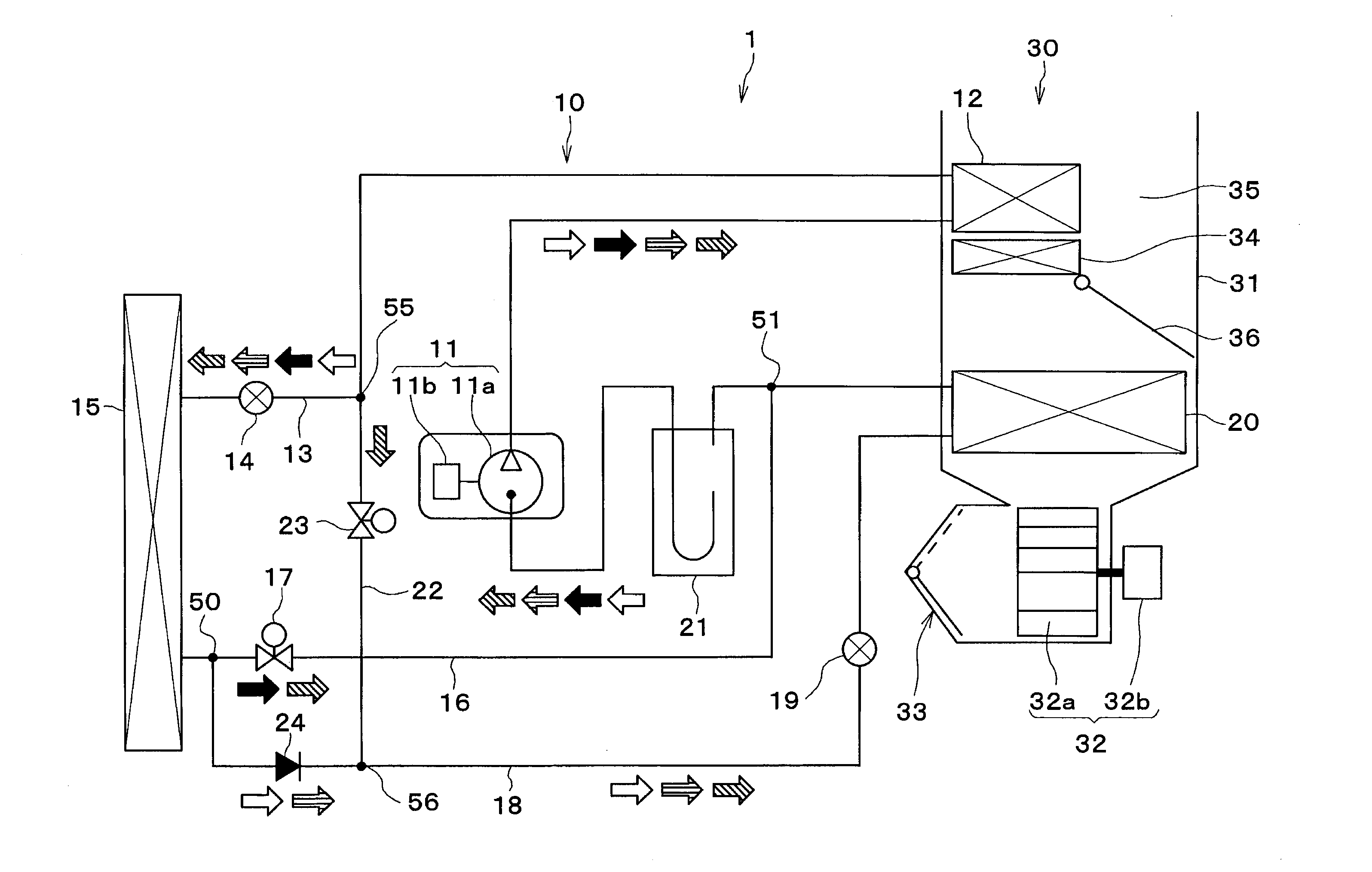
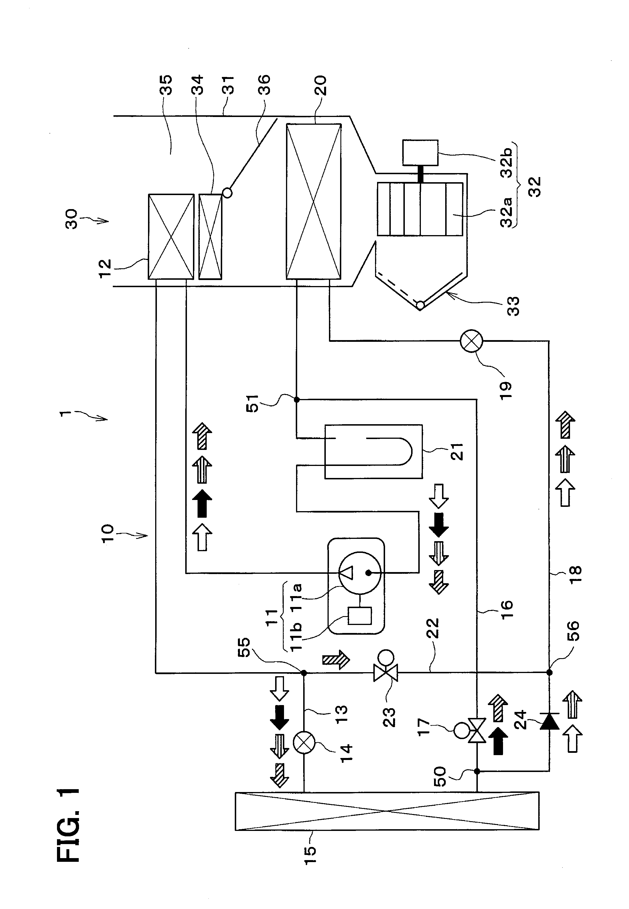
[0049]1 is a schematic configuration drawing illustrating a vehicle air conditioning apparatus 1 of the present embodiment.

[0050]In the present embodiment, a refrigeration cycle device 10 is applied to the vehicle air conditioning apparatus 1 for a hybrid vehicle that obtains a drive force for the traveling of a vehicle from an internal combustion engine (an engine) and a traveling electric motor. The refrigeration cycle device 10 of the vehicle air conditioning apparatus 1 functions to cool or heat air to be blown into the vehicle interior that is a space to be air-conditioned.

[0051]Therefore, the refrigeration cycle device 10 is configured to be capable of switching the refrigerant flow channel among a refrigerant flow channel in a cooling mode (cooling operation) for cooling the vehicle interior, a refrigerant flow channel in a dehumidification heating mode (dehumidification operation) for heating ...

second embodiment

[0142]In the first embodiment described above, the refrigerant flow channel toward the first expansion valve 14 and the refrigerant flow channel toward the second opening-and-closing valve 23 extend in the horizontal direction in the second inlet side connector 55. In a second embodiment, however, as illustrated in FIG. 8, in the second inlet side connector 55, a first refrigerant flow channel 55a leading from the refrigerant inlet port to the refrigerant outlet port connected to the first expansion valve 14 extends to an upper side in the direction of the gravitational force from a lower side in the direction of the gravitational force, and a second refrigerant flow channel 55b branching from the first refrigerant flow channel 55a to the refrigerant outlet port connected the second opening-and-closing valve 23 extends in the horizontal direction.

[0143]In this configuration, in the case where the refrigerant flow rate is a low flow rate, the liquid-phase refrigerant branching to the...

third embodiment

[0144]In the first embodiment, the first inlet side connector 50 and the first opening-and-closing valve 17 are fastened with the bolt, and the first inlet side connector 50 and the fastening plate 591 are fastened with another bolt. In a third embodiment, however, as illustrated in FIG. 9, the first inlet side connector 50, the first opening-and-closing valve 17, the fastening plate 591 are fastened with a single bolt 61. Accordingly, the number of components may be reduced, and the number of assembling steps may be reduced.


PUM


Abstract

A refrigeration cycle device includes a flow channel coupling member which constitutes at least one of a branching portion and a joining portion of a third refrigerant passage and a branching portion and a joining portion of a bypass passage. One of three refrigerant ports of the flow channel coupling member is directly connected to one of two refrigerant ports of a first switching device or a second switching device, and a sealing mechanism preventing a refrigerant leakage is provided in a connecting portion between the refrigerant port of the flow channel coupling member and the refrigerant port of the first switching device or the second switching device. The flow channel coupling member is fixed to one of the switching devices at a position different from a position of the sealing mechanism.

Description

CROSS REFERENCE TO RELATED APPLICATION[0001]This application is based on and incorporates herein by reference Japanese Patent Applications No. 2012-252015 filed on Nov. 16, 2012, No. 2013-186928 filed on Sep. 10, 2013, and No. 2013-213389 filed on Oct. 11, 2013.TECHNICAL FIELD[0002]The present disclosure relates to a refrigeration cycle device applied to an air-conditioning apparatus configured to perform a dehumidification operation in which air blown to a space to be air-conditioned is cooled and dehumidified and the dehumidified blown air is heated.BACKGROUND ART[0003]In the related art, examples of a vehicle air conditioning apparatus provided with a refrigeration cycle include a configuration provided with an evaporator and a condenser arranged in an air conditioning case and an outside heat exchanger arranged on an outside of a vehicle cabin and configured to be capable of switching circuits to one of a refrigerant circuit for a cooling mode, a refrigerant circuit for a heatin...

Claims


Application Information

Patent Timeline
Patent Type & Authority Applications(United States)
IPC IPC(8): F25B13/00
CPCF25B13/00B60H1/3229F25B5/04F25B49/005F25B2400/0409F25B2500/221B60H1/00921F25B41/39F25B41/40F25B41/42
Inventor KITAMURA, KEIICHIHASHIMOTO, SHIHOTANAKA, MITSUYOSHIONO, JUNICHI
Owner DENSO CORP
Why Eureka
Try Eureka