Pellicle inspection apparatus

a technology of pellicle film and inspection apparatus, which is applied in the direction of microlithography exposure apparatus, printers, instruments, etc., can solve the problems of inevitable sagging and wrinkle formation of pellicle film, and achieve the effect of high degree of accuracy

a technology of pellicle film and inspection apparatus, which is applied in the direction of microlithography exposure apparatus, printers, instruments, etc., can solve the problems of inevitable sagging and wrinkle formation of pellicle film, and achieve the effect of high degree of accuracy

US20150293460A1Active Publication Date: 2015-10-15LASERTEC CORP

Image

  • Pellicle inspection apparatus
  • Pellicle inspection apparatus
  • Pellicle inspection apparatus

Examples


Embodiment Construction

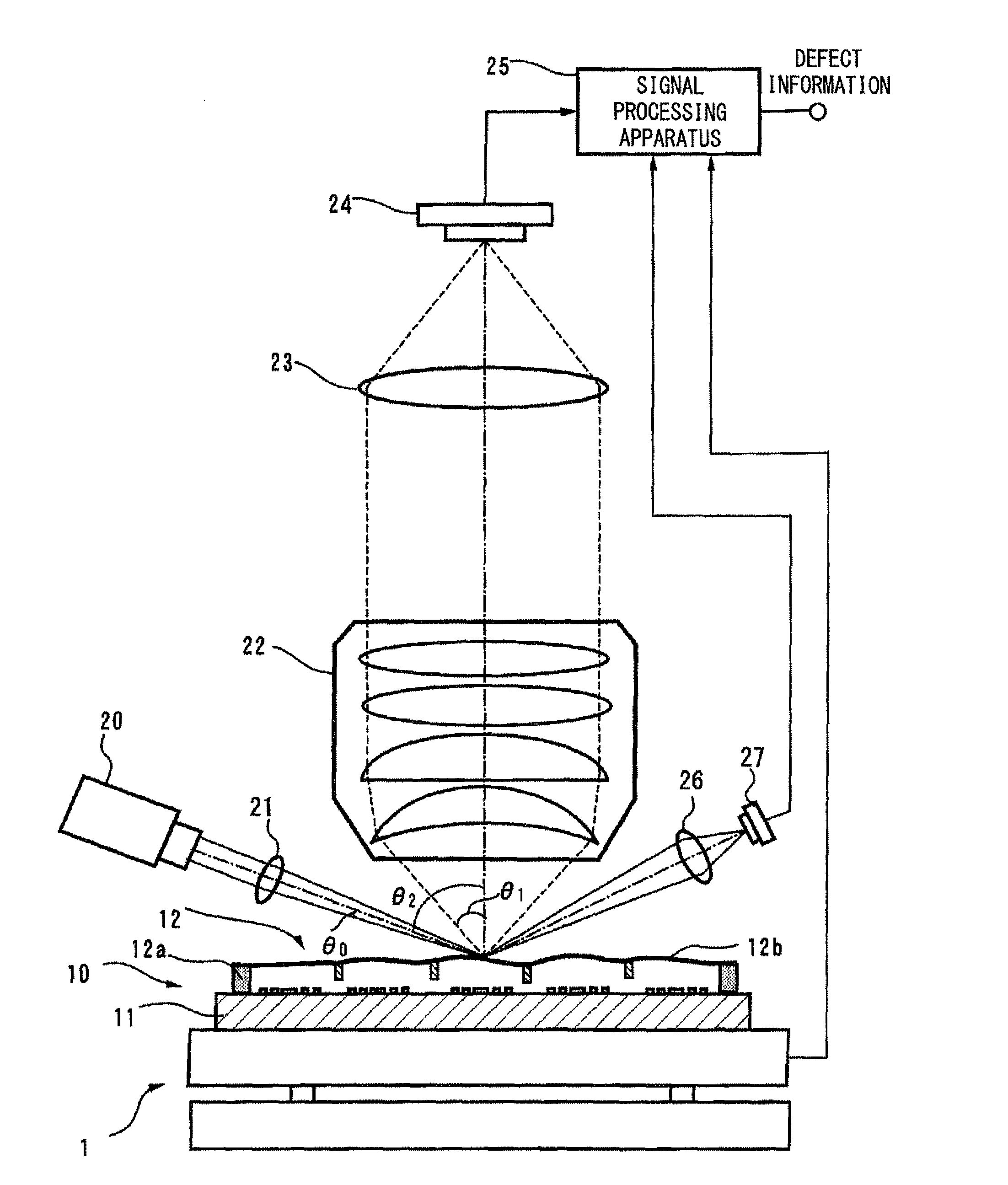
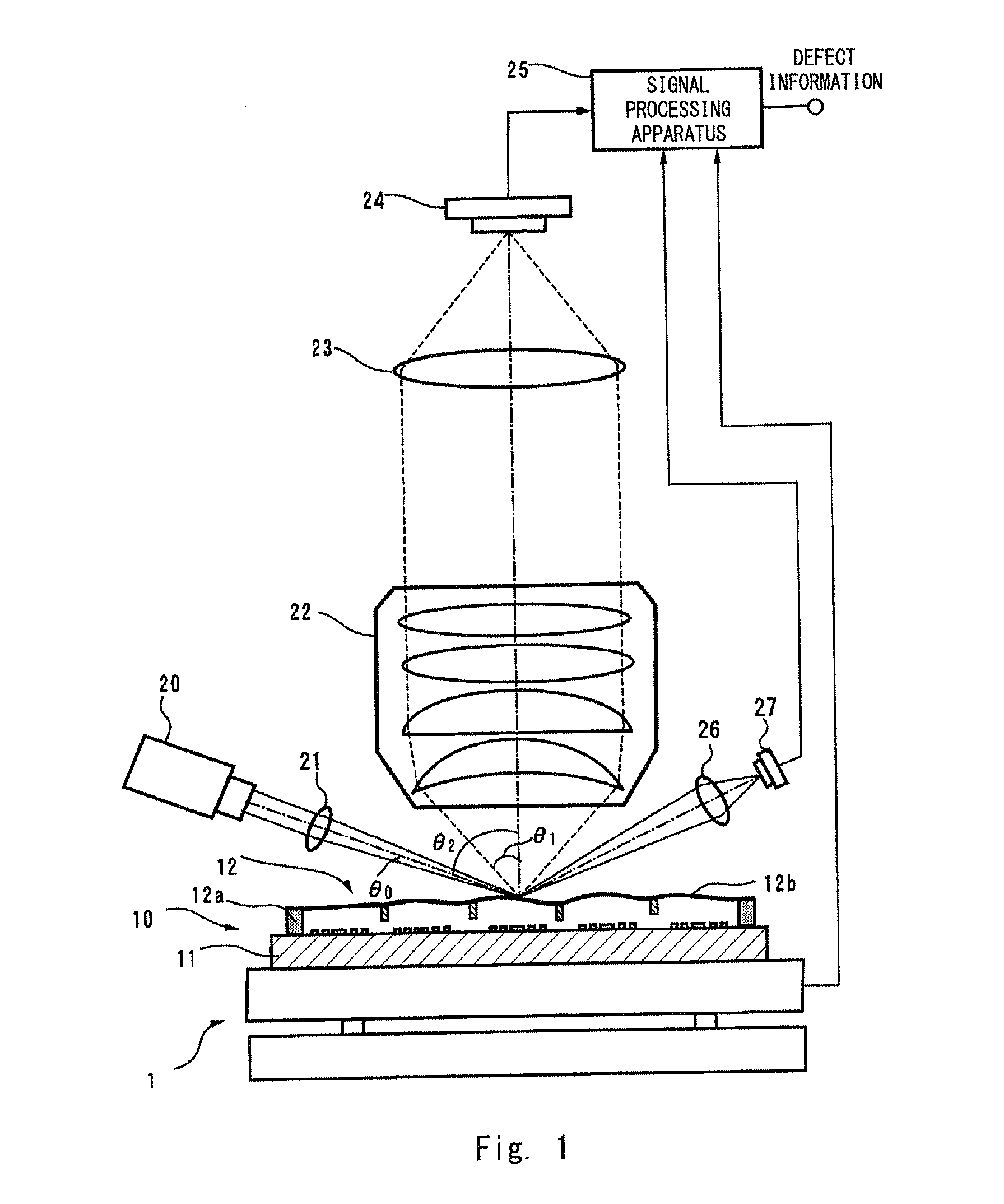
[0036]FIG. 1 is a drawing illustrating an example of a pellicle inspection apparatus that inspects a EUV mask provided with a pellicle used in a semiconductor manufacturing process. In this example, the pellicle inspection apparatus detects foreign substances such as particles present on a pellicle film 12b of an EUV mask 10 provided with a pellicle and a contamination having a thin film form on the pellicle film 12b. The EUV mask 10 provided with a pellicle is arranged on a stage 1. The stage 1 includes an XY stage, and moves in a zigzag state in an X-direction and a Y-direction. In this example, an illuminating beam scans the pellicle film 12b two-dimensionally in association with a stage movement.

[0037]The EUV mask 10 provided with a pellicle includes an EUV mask 11 and a pellicle 12. The EUV mask 11 includes a projected pattern formed thereon. The pellicle 12 covers a patterned area of the EUV mask 11. The pellicle 12 includes a pellicle frame 12a and the pellicle film 12b. The ...


PUM

PropertyMeasurementUnit
wavelengthaaaaaaaaaa
exposure wavelengthaaaaaaaaaa
wavelengthaaaaaaaaaa

Abstract

Provided with a pellicle inspection apparatus that inspects a pellicle film of a mask provided with a pellicle and used in EUV lithography. The pellicle inspection apparatus includes: an illumination optical system that projects a converging illuminating beam toward the pellicle film;a light collection optical system including an object lens having an optical axis substantially orthogonal to the pellicle film and that collects scattering light outgoing from a foreign substance present on the pellicle film; and a detection system that detects the scattering light collected by the light collection optical system, wherein an incident angle θ2 of the illuminating beam with respect to the pellicle film satisfies Expression θ2−θ0>θ1+23°, where θ0 is a collecting angle (half angle) of the illuminating beam, and θ1 is a maximum light-receiving angle (half angle) of the object lens.

Description

INCORPORATION BY REFERENCE[0001]This application is based upon and claims the benefit of priority from Japanese patent application No. 2014-82284, filed on Apr. 11, 2014, the disclosure of which is incorporated herein in its entirety by reference.BACKGROUND OF THE INVENTION[0002]1. Field of the Invention[0003]The present invention relates to a pellicle inspection apparatus and, more specifically, to a pellicle inspection apparatus suitable for inspecting a pellicle film on an EUV mask provided with a pellicle used in an EUVL (Extremely Ultraviolet Lithography) process.[0004]2. Description of Related Art[0005]Currently, ArF lithography is applied to a quantity production in a lithographic technology having a key role in miniaturization of semiconductors. In the ArF lithography, an ArF excimer laser having an exposure wavelength of 193 nm is used as an exposure source. An immersion technology for enhancing a resolution by filling a space between an object lens of an exposure apparatus...

Claims


Application Information

Patent Timeline
15 Oct 2015
Publication
US20150293460A1
IPC
G03F7/20
CPC
G03F7/7065; G03F1/84; G03F1/62
Inventors
TAKEHISA, KIWAMU; TAJIMA, ATSUSHI