Machine tool design method and machine tool design system

a design method and machine tool technology, applied in the direction of design optimisation/simulation, geometric cad, instruments, etc., can solve the problems of lack of theoretical background, large amount of time and money to modify the design, and lack of current design procedure, so as to reduce the burden of engineers

Inactive Publication Date: 2015-10-15
IND TECH RES INST
View PDF1 Cites 24 Cited by
  • Summary
  • Abstract
  • Description
  • Claims
  • Application Information

AI Technical Summary

Benefits of technology

[0008]From the above, the machine tool design method and machine tool design system for the disclosure mainly utilize the structure analysis technique, the chatter stability analysis technique, the parameters optimization technique and so on, further incorporate with design database to aid engineers rapidly design a machine tool. Whether having experience of designing machine tools or not, engineers can design a machine tool for a machining process purpose. It reduces the burden of engineers and further helps them escaping from the restriction of prior experience to propose breakthrough designs.

Problems solved by technology

If the stiffness of the machine is insufficient, it will consume a huge amount of time, labor cost and money to modify the design.
However, the machine tool design is only worthy of use, and it is unable to predict the final performance of the machine tool but results in wasting time and money.
In addition, the current design procedure lacks theoretical background.
The imagination of engineers is restricted by their previous experience thus it is difficult to produce breakthrough designs.
Specifically, the current machine tools design technology is more focused on structural performance optimization and rarely noticed manufacturing optimization, which results in the design result may not be able to satisfy the requirements of the manufacturing process.
However, the designed machine tool may not be able to fulfill the usage requirement if the effect of machine frame structure on the machine performance is not considered.
For example, the generative chatter is an undesired machining phenomenon due to the occurrence of the inverted excitation between the cutting tool and workpiece, which can result in poor surface roughness of the workpiece, shortening the life of cutting tools and even damaging the spindle, and then increasing the machining cost and manufacturing time.
This is a technical issue that the persons who are skilled in the art desperately want to solve.

Method used


Image

  • Machine tool design method and machine tool design system
  • Machine tool design method and machine tool design system
  • Machine tool design method and machine tool design system

Examples


Embodiment Construction

[0017]The detail description of the disclosure is described by specific embodiments in the following. Those with ordinary skills in the arts can readily understand the other functions of the disclosure after reading the disclosure of this specification. The disclosure can also be implemented with different embodiments and examples.

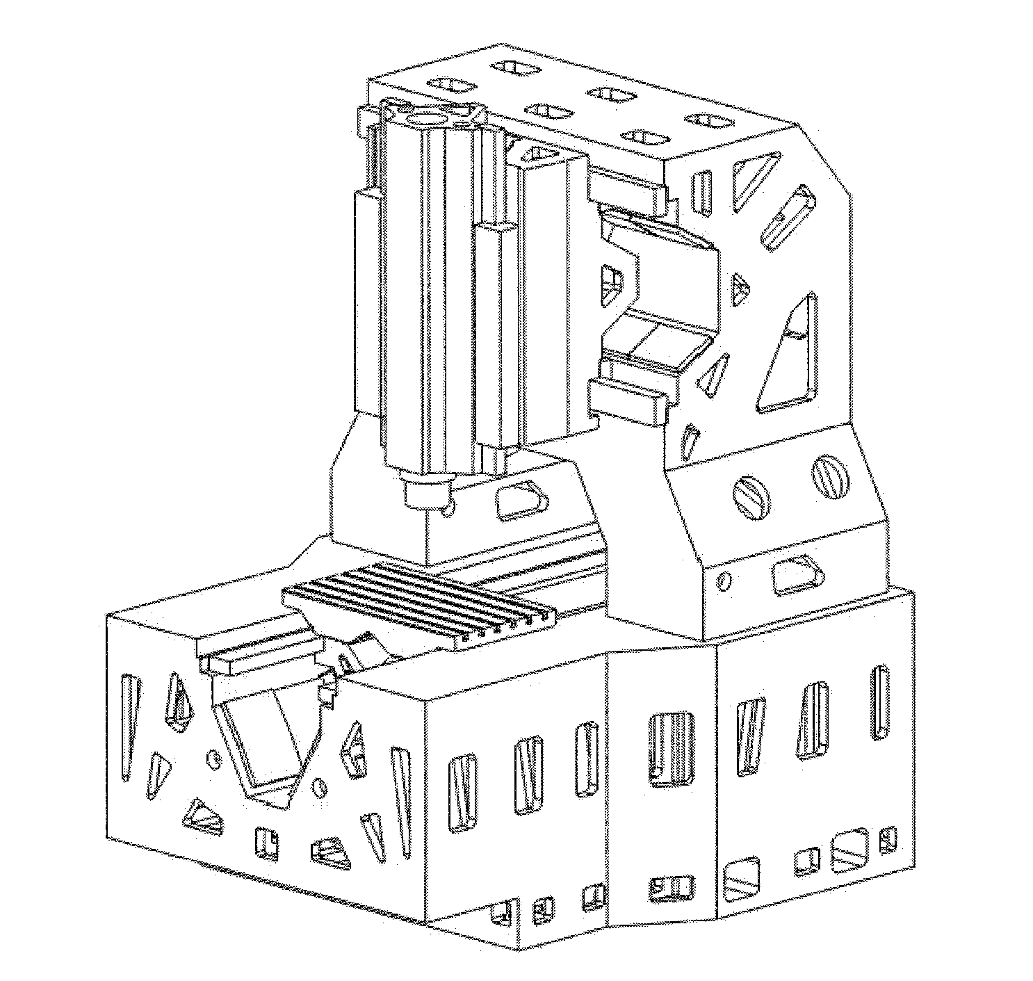
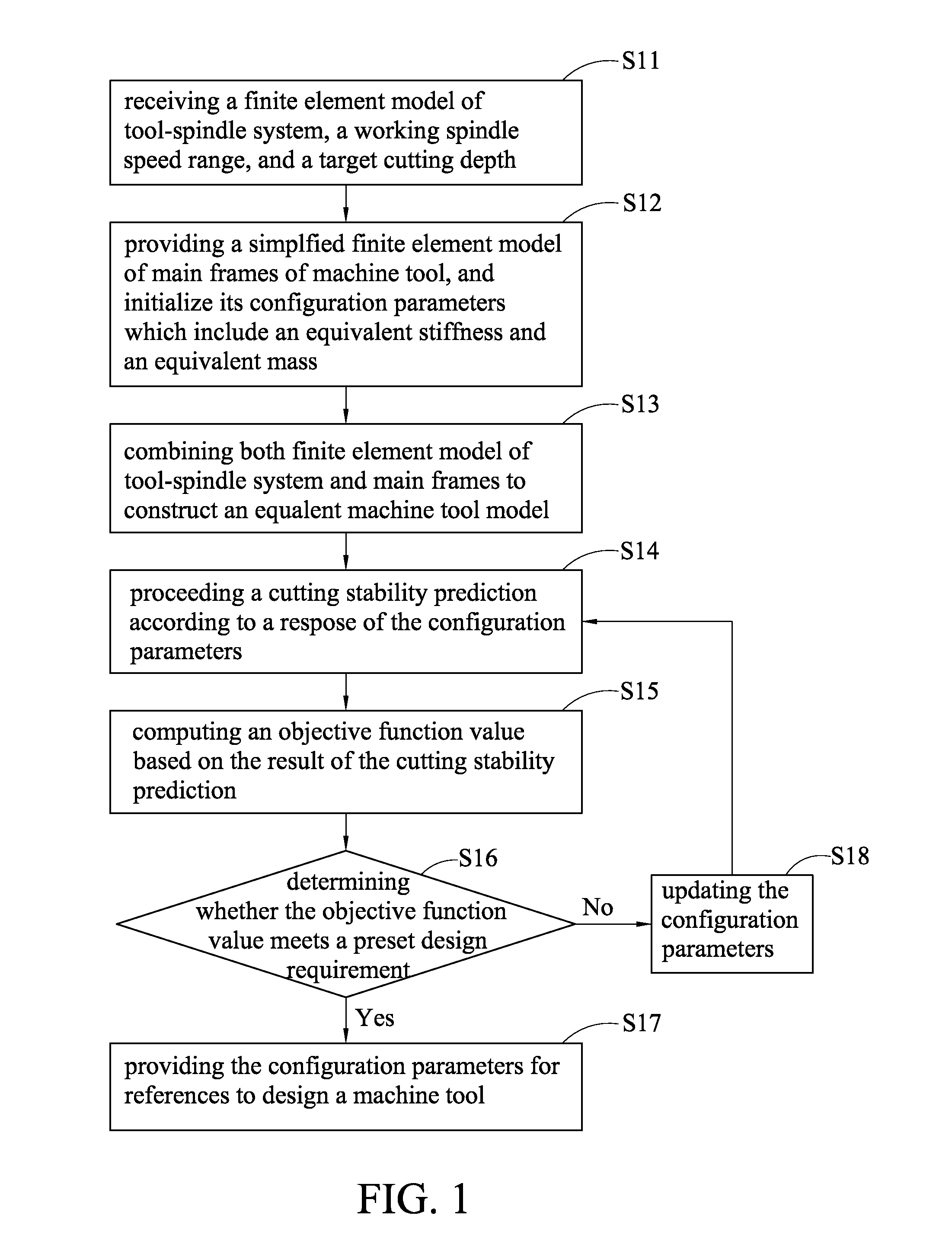
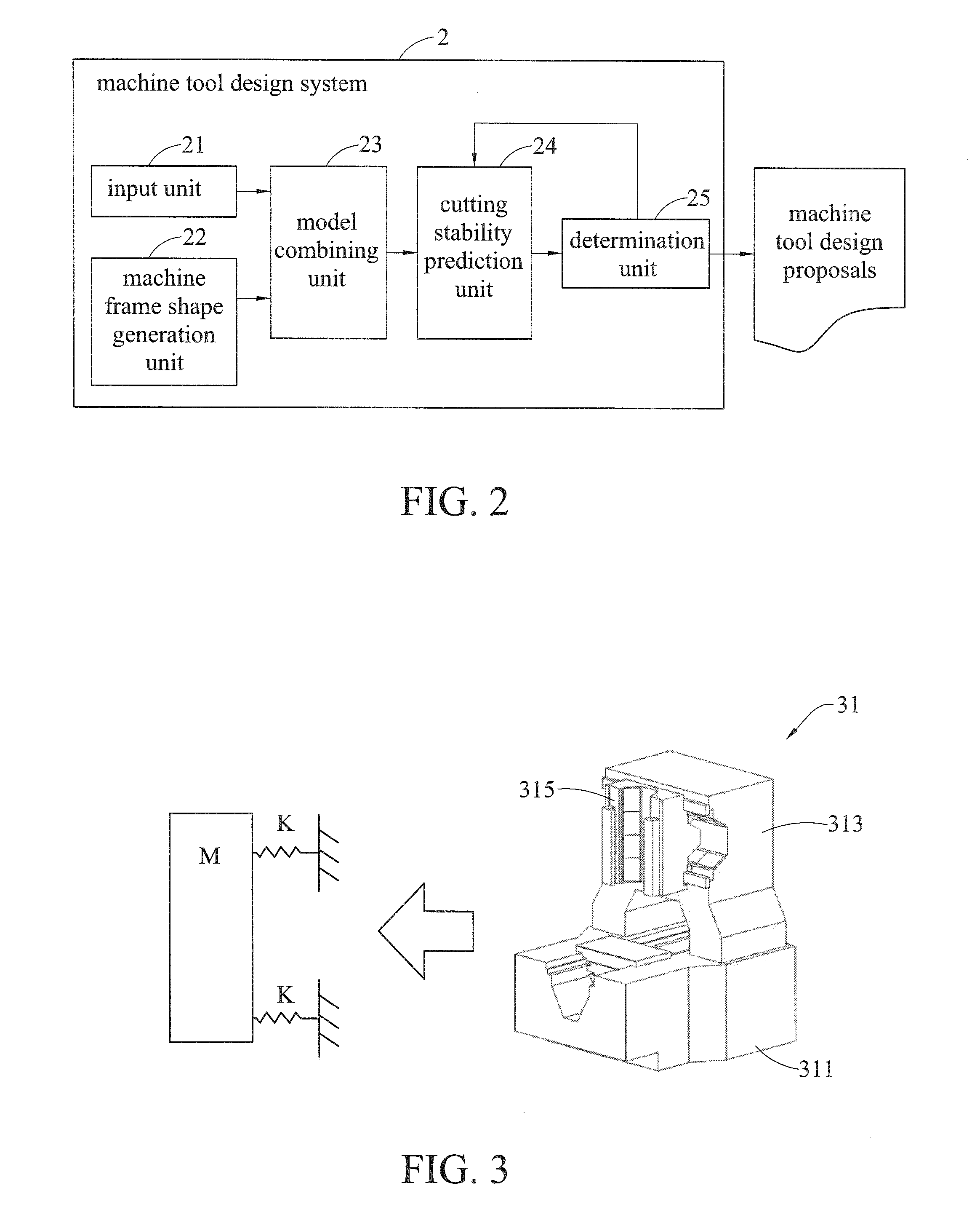
[0018]FIG. 1 is a flow chart depicting the machine tool design method of the disclosure. As shown in the figure, machine tools are designed by providing, for example, the structure analysis technique, the chatter stability analysis technique, the parameter optimization and topology optimization, and incorporating design database aid design. The topology optimization is a mathematical method for designing an optimized material allocation in a given space to achieve a specific purpose under given loading and boundary conditions. For example in machine tools design, the given design space is the solid shape of the machine tool frame structure and the topology...


PUM


Abstract

A machine tool design method includes: receiving a finite element model of tool-spindle system including a cutting tool, a working spindle speed range, and a target cutting depth; providing a simplified finite element model of main frames of machine tool and initializing its configuration parameters including an equivalent stiffness and an equivalent mass; combining the simplified finite element model of main frames of machine tool with the finite element model of tool-spindle system to construct an equivalent machine tool model; according to a response of the configuration parameters, proceeding a cutting stability prediction of the equivalent machine tool model, and computing an objective function value based on a predicted result; and determining whether the objective function value meets a preset design requirement, if yes, employing the configuration parameters to be references to design a machine tool, if not, updating the configuration parameters and proceeding the cutting stability prediction again.

Description

CROSS-REFERENCE TO RELATED APPLICATION[0001]This application claims foreign priority under 35 U.S.C. §119(a) to Patent Application No. 103113362, filed on Apr. 11, 2014, in the Intellectual Property Office of Ministry of Economic Affairs, Republic of China (Taiwan, R.O.C.), the entire content of which Patent Application is incorporated herein by reference.TECHNICAL FIELD[0002]This disclosure relates to a machine tools design technology, and more specifically, relates to a design method and a design system of machine tools.BACKGROUND OF THE INVENTION[0003]Currently, the design procedure of modern machine tools usually depends on the experience. To test the cutting ability of a machine, the cutting performance test is conducted after completing manufacturing and assembling the machine. If the stiffness of the machine is insufficient, it will consume a huge amount of time, labor cost and money to modify the design. However, the machine tool design is only worthy of use, and it is unabl...

Claims


Application Information

Patent Timeline
Patent Type & Authority Applications(United States)
IPC IPC(8): G06F17/50
CPCG06F17/5018G06F17/50G06F30/17G06F30/23
Inventor LIAO, CHIEN-CHIHLIN, CHIN-TECHEN, PEI-YINLUO, TZUO-LIANG
Owner IND TECH RES INST
Why Eureka
Try Eureka