
Trip planning and management methods for an intelligent transit system with electronic guided buses

a technology of intelligent transit and electronic guided buses, applied in the direction of navigation instruments, external condition input parameters, non-deflectable wheel steering, etc., can solve the problems of reducing the traffic capacity of other vehicles, and the subway system is usually very expensive, so as to maximize the transit's capacity and efficiency, and not increase the workload of drivers.

Inactive Publication Date: 2015-10-15
TOMORROWS TRANSPORTATION TODAY
View PDF0 Cites 51 Cited by
  • Summary
  • Abstract
  • Description
  • Claims
  • Application Information

AI Technical Summary

Benefits of technology

The patent describes a trip management method for electronic guided buses that can dynamically update or determine the track to follow so as to automatically carry out the assigned trip without increasing the workload of the drivers. This allows greater freedom for the transit dispatch center to dynamically define and update trips so as to maximize the transit' capability in meeting ridership needs without increasing the cost of transit operations. The intelligent transit system can effectively meet the riders' needs while maximizing the transit's capability and efficiency.

Problems solved by technology

Subways have been built in various metropolitan areas; however, subway systems are usually very expensive and therefore are typically adopted to meet a very large ridership demand.
Although light rail systems are cheaper than subways, they are still far from low cost and require dedicated lanes for the rails, which reduces the traffic capacity for other vehicles.
However, regular buses cannot provide performances (such as the docking performance at stations) comparable to rail systems.
However, vision-based systems have difficulties in poor visibility conditions such as fog, rain, and snow.
However, the DGPS-based systems likely suffer from signal blockage and multipath when the vehicle travels by tall buildings, tunnels, and under dense trees.
For example, if two magnet tracks directly cross each other, the magnets at the crossing point would be close to one another, causing interference of their magnetic fields.
As a result, the position estimates based on the magnetic field measurement do not reflect the true position of the bus with respect to either magnetic marker, causing difficulties for the electronic guided bus to follow either track.

Method used


Image

  • Trip planning and management methods for an intelligent transit system with electronic guided buses
  • Trip planning and management methods for an intelligent transit system with electronic guided buses
  • Trip planning and management methods for an intelligent transit system with electronic guided buses

Examples


Embodiment Construction

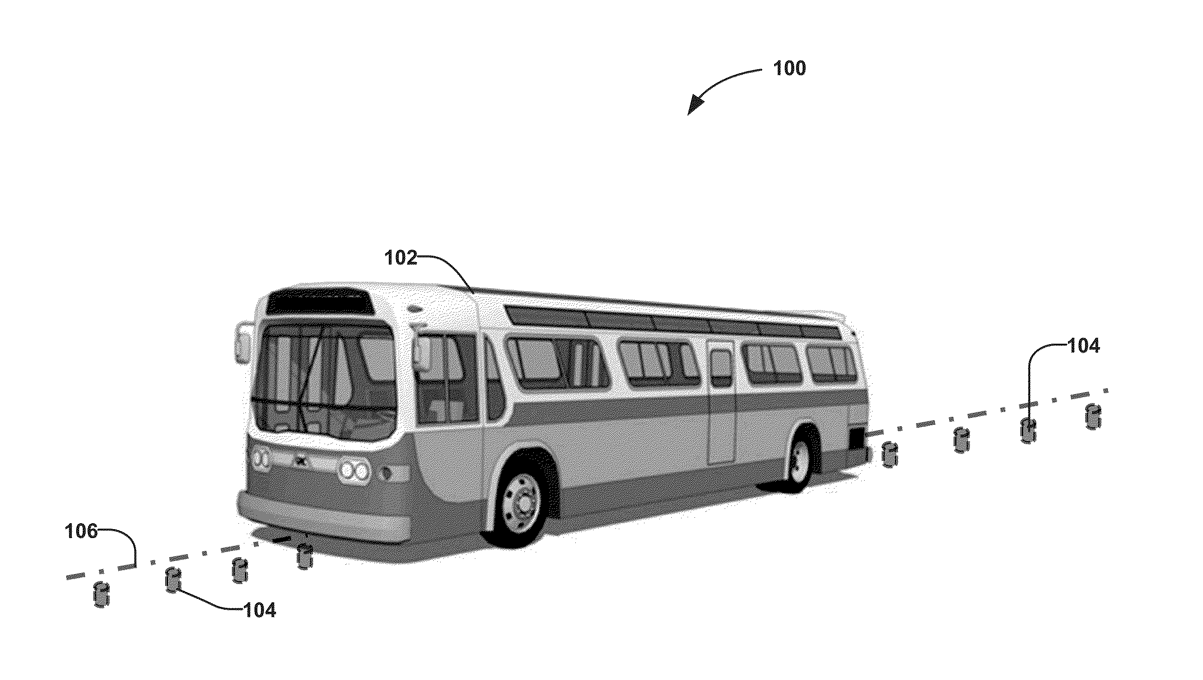
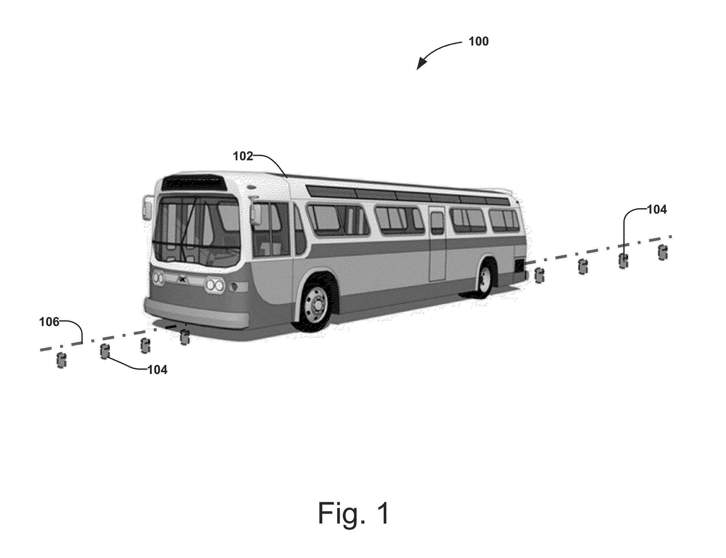
[0054]FIG. 1 shows an electronic guided bus 102, which is capable of following a magnet track 106 defined by magnetic markers 104 installed in the roadway. The magnetic markers 104 are usually permanent magnets and are typically installed under the road surface with one polarity (either north pole or south pole) facing upward. The magnetic markers 104 may be installed along the lane centerline or with a predefined offset (or predefined offsets) to the lane centerline. The distance between the magnetic markers 104 may be a fixed distance (e.g., 1 m) and may also vary depending on road curvature or other considerations.

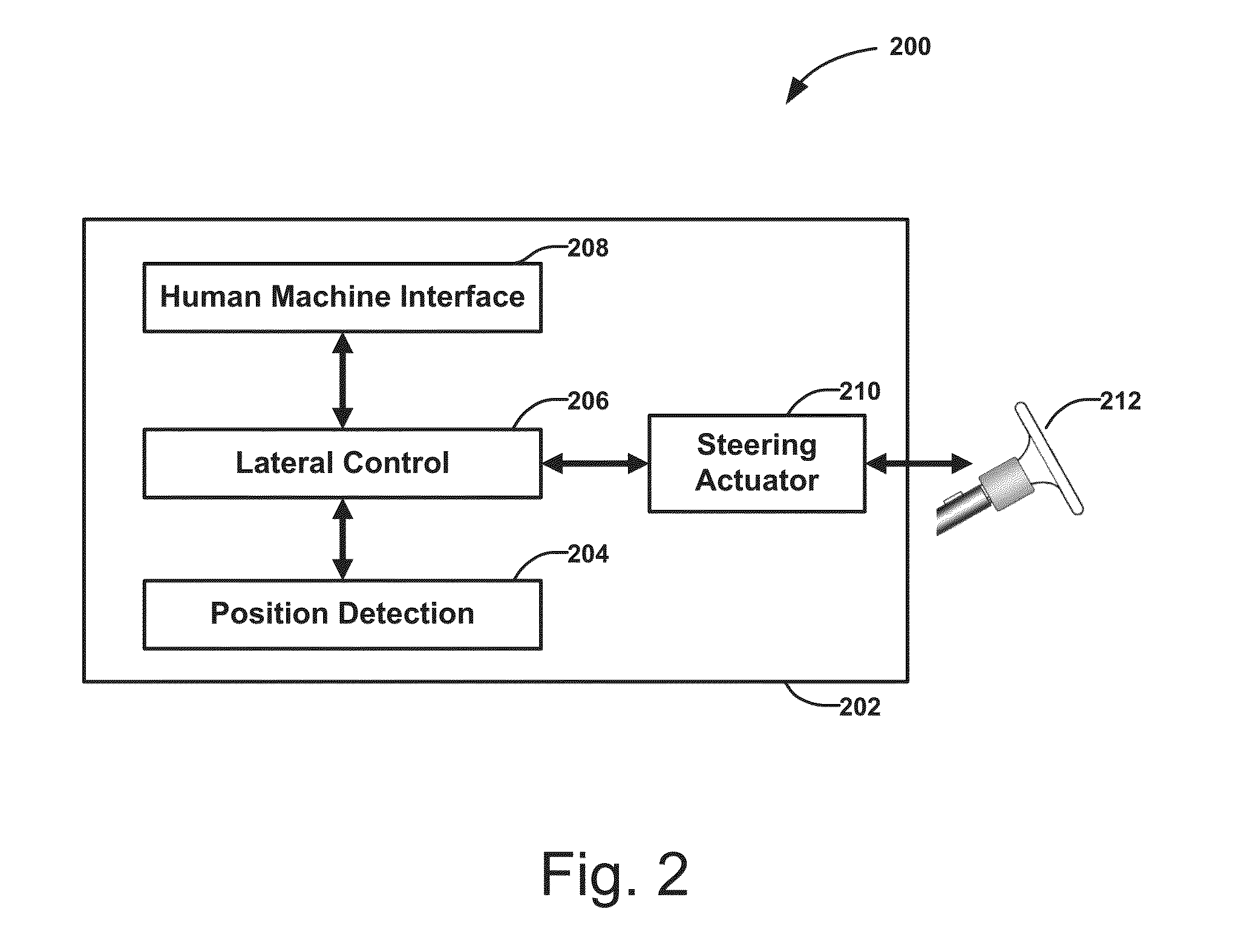
[0055]FIG. 2 is a block diagram 200 of an electronic guidance system 202 on-board the electronic guided bus 102. The electronic guidance system 202 is capable of guiding the bus 102 through the magnet track 106 defined by the magnetic markers 104. The position sensing unit 204 determines the lateral deviation of the bus 102 with respect to the magnet track 106, and sinc...


PUM


Abstract

A method for trip management provided for an electronic guided bus that follows an electronic track. The method comprises receiving an assigned trip from a bus dispatch system, obtaining junction information based on the assigned trip, obtaining a current location of the electronic guided bus, identifying a junction the bus is at based on the current location of the bus and the junction information, and setting a main track for the bus to follow based on the desired track for the identified junction. The method provides an intelligent transit system in which dispatch processors estimate ridership demands based on the passengers' trip information, determine a plurality of trips based on estimated ridership demands, generate dispatch schedule for the trips, assign trips to the electronic guided buses, and communicate assigned trips to the electronic guided buses via communication devices.

Description

BACKGROUND[0001]1. Technical Field[0002]The present invention relates to methods and systems for dynamic dispatch of electronic guided buses based on real-time ridership demands and traffic conditions. More specifically, the present invention provides methods for electronic guided buses to choose an appropriate electronic track to follow based on their assigned trips and for a dispatch system to dynamically plan the trips and determine a dispatch schedule for bus transit based on real-time demands of ridership.[0003]2. Related Art[0004]The development of a low-cost, efficient, high-performance public transit system for urban cities has attracted lots of interest for decades. Subways have been built in various metropolitan areas; however, subway systems are usually very expensive and therefore are typically adopted to meet a very large ridership demand. Some cities have chosen to build light rail transportation systems, which combine the attractiveness of traditional railways with th...

Claims


Application Information

Patent Timeline
Patent Type & Authority Applications(United States)
IPC IPC(8): G08G1/133B62D15/02G01S19/13
CPCG08G1/133B62D15/025G01S19/13G05D1/0261B60W30/10G08G1/127G08G1/20G08G1/207B60W2300/10B60W2710/20B60W2556/55B60W2556/50B60W60/001G01S5/0295G01S5/0269
Inventor HUANG, JIHUATAN, HAN-SHUEZHANG, WEI-BIN
Owner TOMORROWS TRANSPORTATION TODAY
Learn More