Method and system for treating water inboard a vessel

a technology for treating water and water inboard a vessel, applied in water cleaning, specific water treatment objectives, water/sludge/sewage treatment, etc., can solve the problems of affecting the survival of the environment, introducing and spreading non-native organisms, and undesirable effects

a technology for treating water and water inboard a vessel, applied in water cleaning, specific water treatment objectives, water/sludge/sewage treatment, etc., can solve the problems of affecting the survival of the environment, introducing and spreading non-native organisms, and undesirable effects

US20150298990A1Inactive Publication Date: 2015-10-22ULMATEC PYRO

Image

  • Method and system for treating water inboard a vessel
  • Method and system for treating water inboard a vessel
  • Method and system for treating water inboard a vessel

Examples


Embodiment Construction

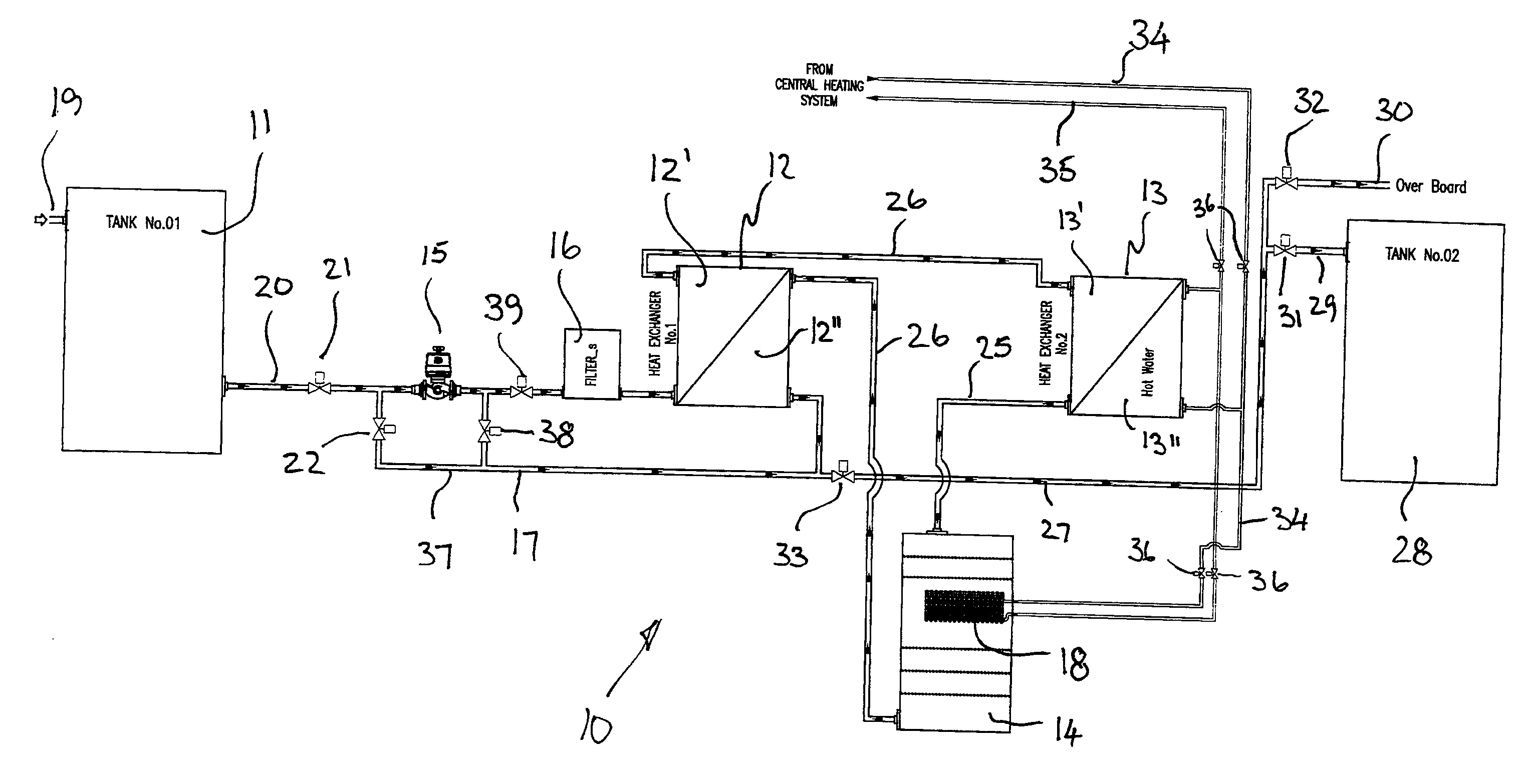
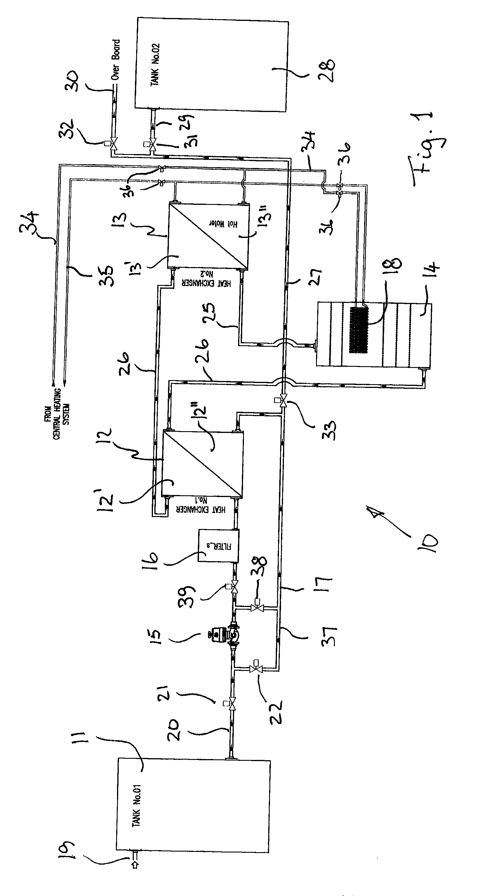
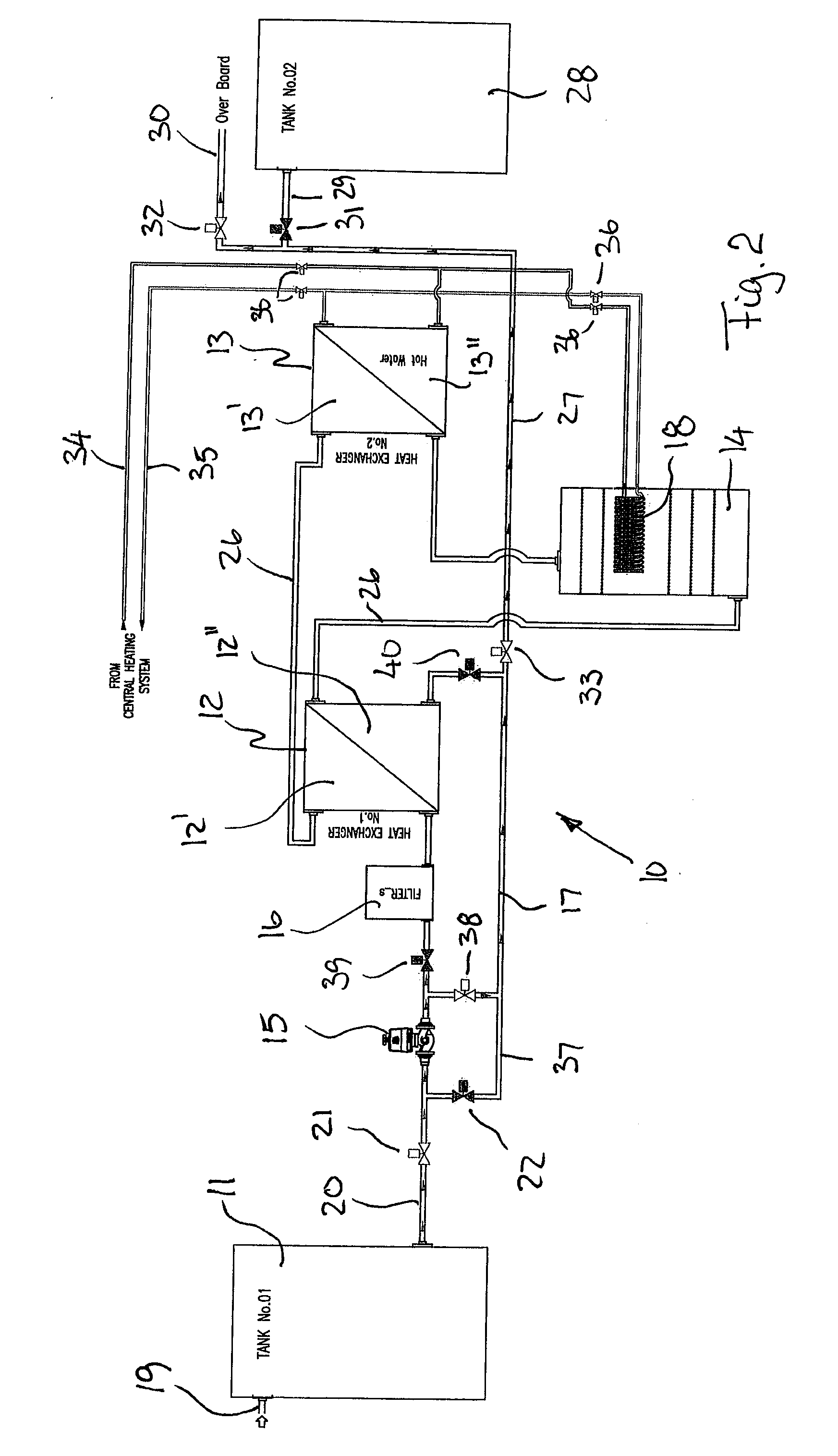
[0038]FIG. 1 shows schematically a flow diagram of the water treatment system 10 according to the present invention. The system 10 is intended for sterilizing different types of waste water and ballast water, based on a pasteurization method. The water to be treated is pumped from one contaminated tank 11, hereafter denoted as the first tank 1, or directly from sea, through a heat receiving section 12′ of a primary heat exchanger 12 where the contaminated water is heated and thereupon through a heat receiving section 13′ of a second heat exchanger 13 where the water is heated even further to a temperature above the pasteurization temperature. Water may be supplied to the first tank 11, for example from the sea, through an inlet. The secondary heat exchanger 13 is heated by supplying thermal fluid delivered to a heat delivery section 13″ of the secondary heat exchanger 13 from the central heating system (not shown). The thermal medium delivering heat to the heat delivery section 13″ ...


PUM

PropertyMeasurementUnit
temperatureaaaaaaaaaa
heataaaaaaaaaa
stabilityaaaaaaaaaa

Abstract

A method and a system for treating water on board a vessel before discharging such water to the sea. The water to be treated is pumped through a primary heat exchanger (12) where the water is pre-heated and then through a secondary heat exchanger (13) where the water is further heated, the secondary heat exchanger (13) being heated by thermal fluid from a central heating system primarily heated by heat recovered from different type of heat generating equipment and also possibly by fuel and / or electricity in cases where the heat recovered from the heat generating systems is not sufficient to treat the water in a sufficient manner.

Description

TECHNICAL FIELD OF THE INVENTION[0001]The present invention relates to a method and a system for treating ballast and waste water onboard vessels prior to discharging such water to the sea, the system comprising a ballast water tank, one or more pumps (15) and an associated piping and valve system for transport of the water to be treated.BACKGROUND FOR THE INVENTION[0002]Vessels depend on ballast water to provide stability and also maneuverability during a voyage. Such ballast water may be taken on at one port where for example cargo is unloaded and discharged to sea at another port when the vessel is loaded again.[0003]In aqua farming or aquaculture, it is common to use transport vessels for transporting living aquatic biomass, such as salmon, in water filled tanks from production nets, cages or cultivation enclosures for example to an abattoir, either onboard a larger vessel or onshore. To facilitate such transport the living aquatic biomass is pumped from the production nets to t...

Claims


Application Information

Patent Timeline
22 Oct 2015
Publication
US20150298990A1
IPC
C02F1/02; B63J4/00
CPC
C02F1/02; C02F2303/04; B63J4/002; B63J3/00; B63J4/006; C02F2103/008; C02F2103/20; C02F2303/24
Inventors
URKE, JAN PETTER