Filter and method of ultrafiltration

a filter and ultrafiltration technology, applied in the direction of stationary filter elements, water treatment locations, water/sludge/sewage treatment, etc., can solve the problems of membrane damage, filter is no longer functional, and bubble formation

Inactive Publication Date: 2015-10-22
BWT AG
View PDF5 Cites 7 Cited by
  • Summary
  • Abstract
  • Description
  • Claims
  • Application Information

AI Technical Summary

Benefits of technology

[0044]In a modification of the invention, the filter for ultrafiltration comprises a biocidal contact material on the permeate side, i.e. at the outlet. A biocidal contact material refers to a material which has a bactericidal and / or fungicidal effect when being contacted with water.
[0045]In particular silver, for example provided in form of a silver mesh, is considered. A biocidal material at the outlet prevents the formation of germs, algae, or fungi after the elimination of microbes by the membrane pack. In particular, the connection of a silver mesh which forms the final layer of the filter on the permeate side achieves the desired biocidal properties in a simple manner.

Problems solved by technology

However, it has been found that the employed drinking water often contains gases, for example carbonic acid or carbon dioxide, or even air, as a result of outgassing media which cause bubble formation in and blocking of the filter.
When bubbles pass through the filter, it can be concluded that the membrane is damaged and the filter is therefore no longer functional.
This leads to the problem that prior art filters for ultrafiltration are only of limited use for applications in which the water to be sterilized passes through the filter by its own gravity.
Generally, prior art filters for ultrafiltration are not suitable for water that includes added carbonic acid.
However, these approaches do not permit to reliably remove bacteria from the drinking water.
Because of the outgassing activated carbon and the carbonic acid or carbon dioxide produced during the ion exchange, prior art ultrafilters cannot be used downstream water filters, since the ultrafilters would be blocked due to the gases.
However, this may have adverse impacts on the water.
In addition, in a gravity-operated filter the disinfectant is usually not continuously released, so that a sufficient effect is not always guaranteed throughout the entire lifetime of the filter material.
Furthermore, it is known that water dispensers having a storage tank, which are often designed to dispense cooled and / or non-cooled water, involve a risk of microbial multiplication in the water.
This procedure is time-consuming and energy-intensive.
Further, microbes may develop in particular even in the vicinity of the outlet of the water dispenser, which will naturally not be reached by the heated water, but flushed out when actuating the water dispenser.

Method used


Image

  • Filter and method of ultrafiltration
  • Filter and method of ultrafiltration
  • Filter and method of ultrafiltration

Examples


Embodiment Construction

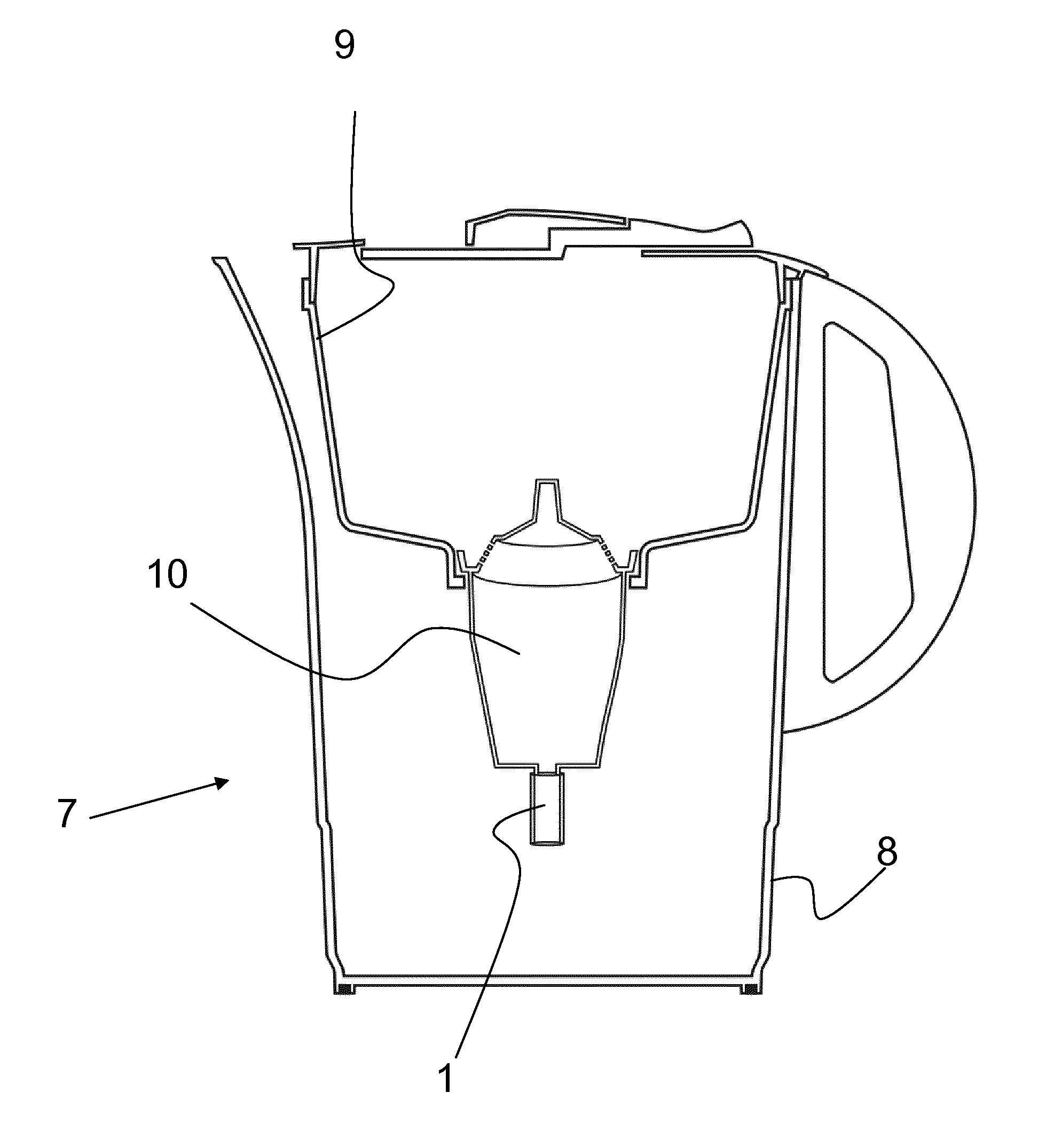
[0071]The invention will now be explained in more detail by way of schematically illustrated exemplary embodiments with reference to the drawings of FIG. 1 to FIG. 7.

[0072]FIG. 1 is a schematic view of a filter 1 for ultrafiltration.

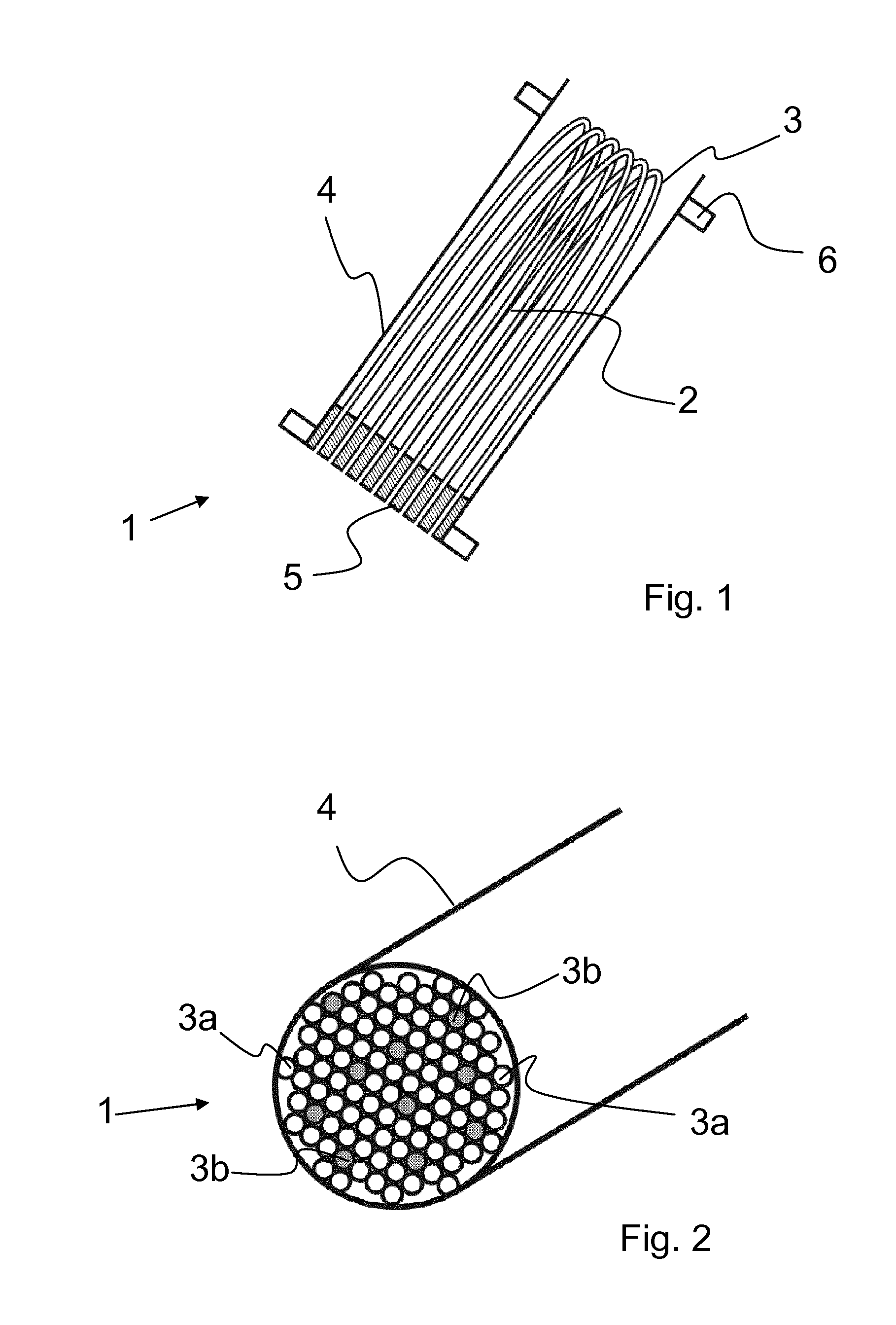
[0073]Filter 1 for ultrafiltration comprises a membrane pack 2 which is arranged in a sleeve 4 preferably formed from plastics.

[0074]The membranes of membrane pack 2 are provided as a bundle made of capillary membranes 3, which bundle is folded once.

[0075]The membranes are bent within sleeve 4 and are embedded in a potting compound 5 on the permeate side. The open end of capillary membranes 3 therefore defines the outlet.

[0076]It will be understood that only a few capillary membranes are shown in this schematic view, and that filter 1 for ultrafiltration comprises a multitude of capillary membranes 3.

[0077]Sleeve 4 comprises fastening means 6 which may for example be provided in form of a bayonet mount or a thread.

[0078]FIG. 2 schematically illustrates t...


PUM

PropertyMeasurementUnit
pore diameteraaaaaaaaaa
diameteraaaaaaaaaa
diameteraaaaaaaaaa

Abstract

A filter for ultrafiltration, which filter comprises a membrane pack having partially hydrophobic membranes.

Description

FIELD OF THE INVENTION[0001]The invention relates to a method and a filter for ultrafiltration. In particular, the invention relates to a filter for water treatment, which includes outgassing filter media such as activated carbon or ion exchangers, which produce carbonic acid and therefore also undissolved carbon dioxide through the exchange of hydrogen ions with hydrogen carbonate ions of drinking water. The invention relates to both gravity-operated and pressure-operated water filters.BACKGROUND OF THE INVENTION[0002]Devices and methods for ultrafiltration are well known. For this purpose, in particular membranes are used to separate particles, in particular of a particle size from 0.01 to 0.001 microns. Such devices are mainly used in pharmacy and medicine.[0003]It is also known that filters for ultrafiltration allow to sterilize liquids, since bacteria normally cannot pass through such a filter. For this purpose, sterile ultrafilters are used. In particular, capillary membranes ...

Claims


Application Information

Patent Timeline
Patent Type & Authority Applications(United States)
IPC IPC(8): C02F1/44B01D61/14B01D61/18
CPCC02F1/444C02F2307/04B01D61/145B01D61/18A61L2/022B01D63/024C02F1/003C02F1/283C02F1/505B01D2311/04B01D2311/2623B01D2311/2626B01D2311/2649B01D2319/06B01D2325/36B01D2325/38B01D2325/48C02F2001/425
Inventor JOHANN, JUERGENBISSEN, MONIQUEBAUER, BERND
Owner BWT AG
Why Eureka
Try Eureka