Refrigeration cycle apparatus

a cycle apparatus and refrigerant technology, applied in the field of refrigeration cycle apparatus, can solve the problems of insufficient heat absorption of refrigerant outside air, inability to adequately reheat the air at the interior condenser, etc., to improve the mechanical efficiency (compression efficiency) of the compressor, improve the cycle coefficient of performance, and improve the heat dissipation efficiency

Active Publication Date: 2015-10-22
DENSO CORP
View PDF4 Cites 27 Cited by
  • Summary
  • Abstract
  • Description
  • Claims
  • Application Information

AI Technical Summary

Benefits of technology

[0018]With this arrangement, in the dehumidification-air heating mode, the refrigerant circuit can be configured such that the refrigerant outlet side of the exterior heat exchanger communicates with the heating side refrigerant suction port of the heating side ejector, and that the refrigerant inlet side or refrigerant outlet side of the cooling heat exchanger communicates with the outlet side of the heating side pressure-increasing portion of the heating side ejector. Thus, the heating capacity of the air in the dehumidification-air heating mode can be improved, similarly to the above-mentioned refrigeration cycle apparatus.
[0019]Further, the refrigeration cycle apparatus of the present disclosure constitutes the so-called economizer refrigeration cycle that causes the compressor to merge the refrigerant being pressurized with an intermediate-pressure refrigerant in the cycle, and thus can improve a mechanical efficiency (compression efficiency) of the compressor, thereby improving the cycle coefficient of performance (COP) of the refrigeration cycle apparatus.
[0020]In the refrigeration cycle apparatus of the present disclosure, the cooling side decompressor may be a cooling side ejector that includes a cooling side nozzle portion decompressing the other of the refrigerants branched by the branch portion, a cooling side refrigerant suction port that draws a refrigerant by a suction effect of an injection refrigerant injected from the cooling side nozzle portion, and a cooling side pressure-increasing portion raising a pressure of a mixed refrigerant of the injection refrigerant injected from the cooling side nozzle portion and the suction refrigerant drawn from the cooling side refrigerant suction port. In the dehumidification-air heating mode, the refrigerant flowing out of the cooling side pressure-increasing portion may flow into the cooling heat exchanger, and the refrigerant flowing out of the cooling heat exchanger may flow into the cooling side refrigerant suction port.
[0021]Thus, the power consumption of the compressor can be suppressed by the pressurizing effect of the cooling side ejector, thereby further improving the COP.

Problems solved by technology

As a result, the refrigerant cannot absorb the sufficient heat from the outside air at the exterior heat exchanger, and thus cannot adequately reheat the air at the interior condenser.

Method used


Image

  • Refrigeration cycle apparatus
  • Refrigeration cycle apparatus
  • Refrigeration cycle apparatus

Examples


first embodiment

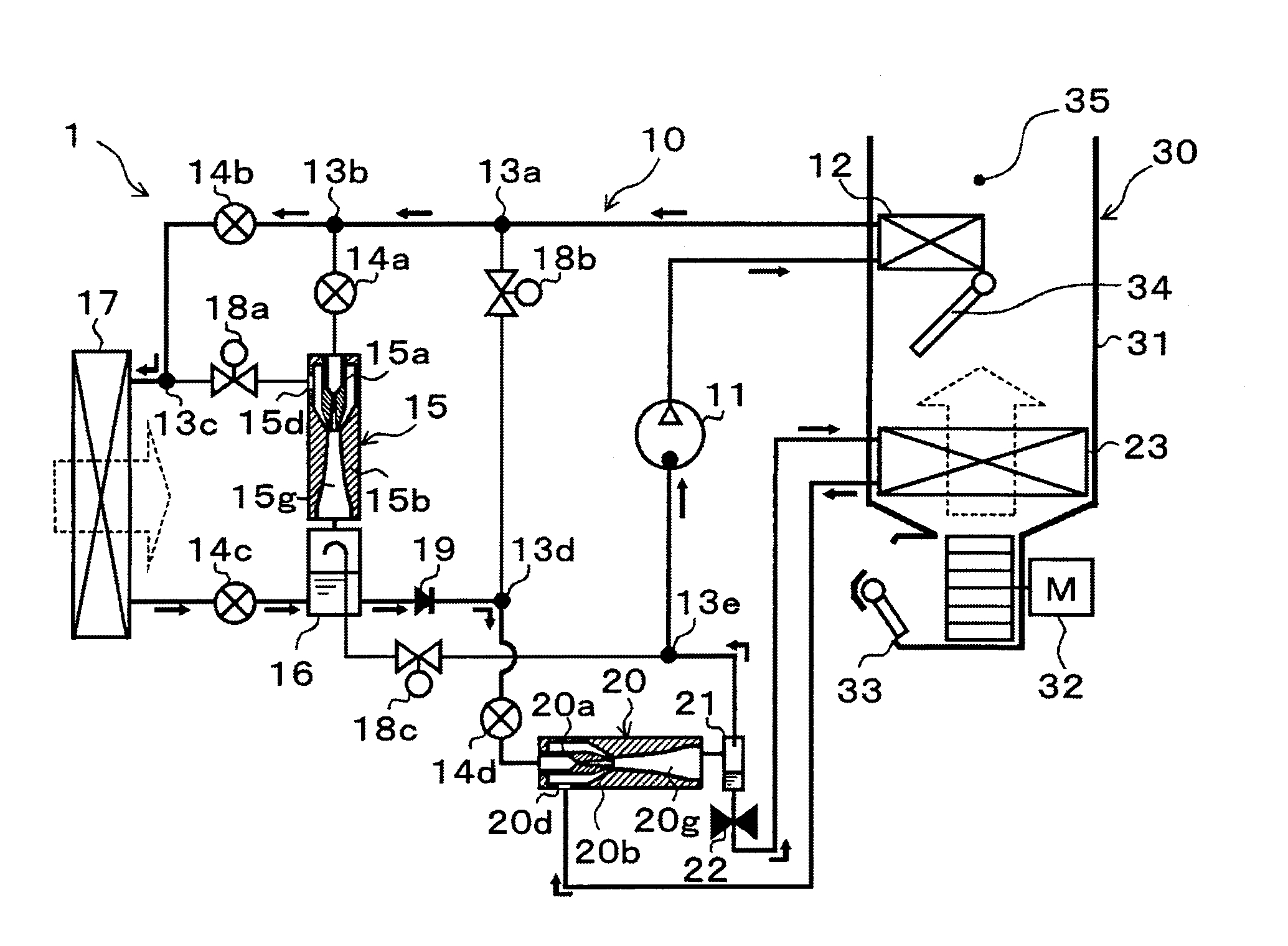
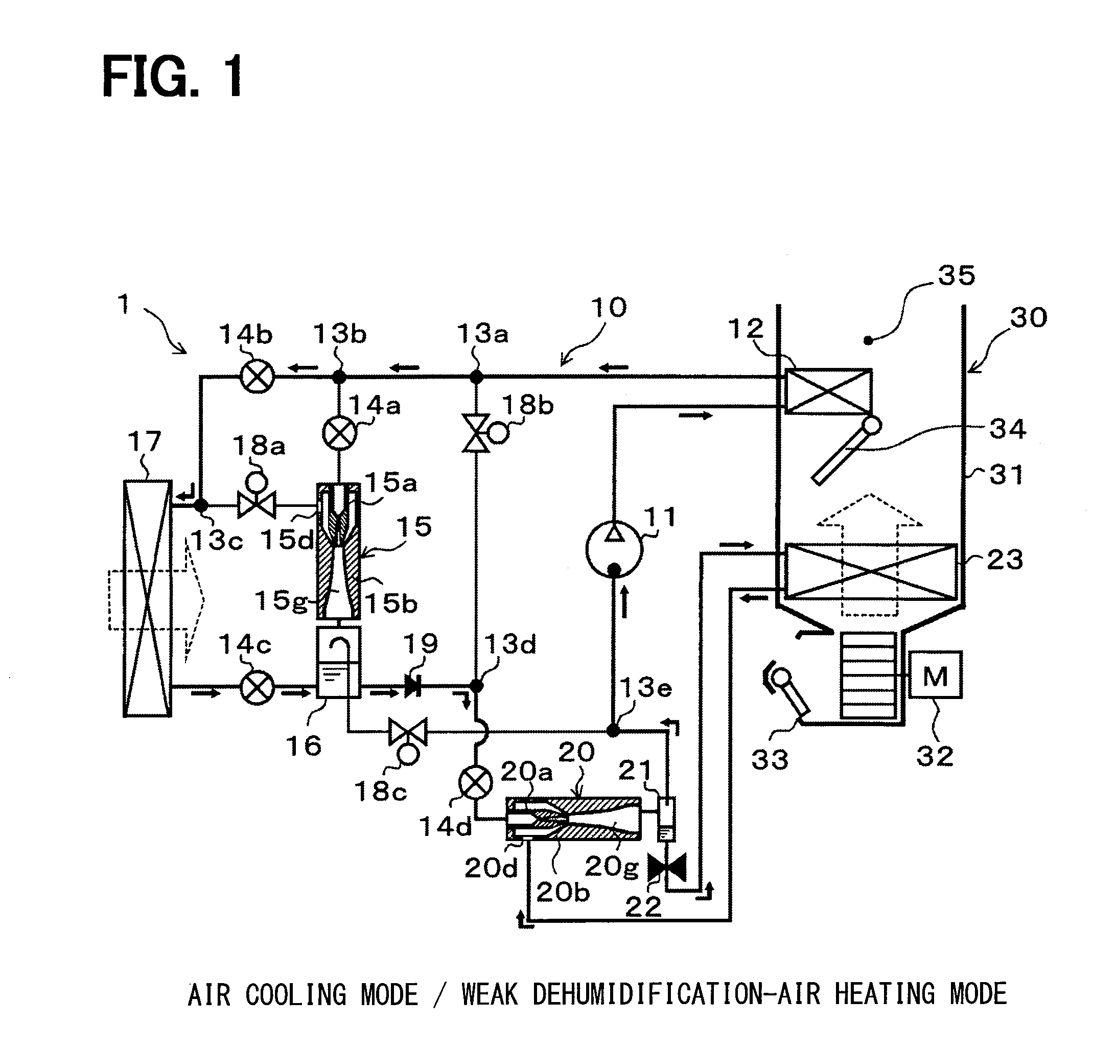
[0059]A first embodiment of the present disclosure will be described below with reference to FIGS. 1 to 11. A refrigeration cycle apparatus 10 of the present disclosure is applied to a vehicle air conditioner 1 to be mounted on an electric vehicle, which is designed to obtain a driving force for vehicle traveling from an electric motor for traveling. The refrigeration cycle apparatus 10 serves to heat or cool air to be blown into a vehicle interior as a space to be air-conditioned in the vehicle air conditioner 1. Here, air is a fluid to be heat-exchanged.

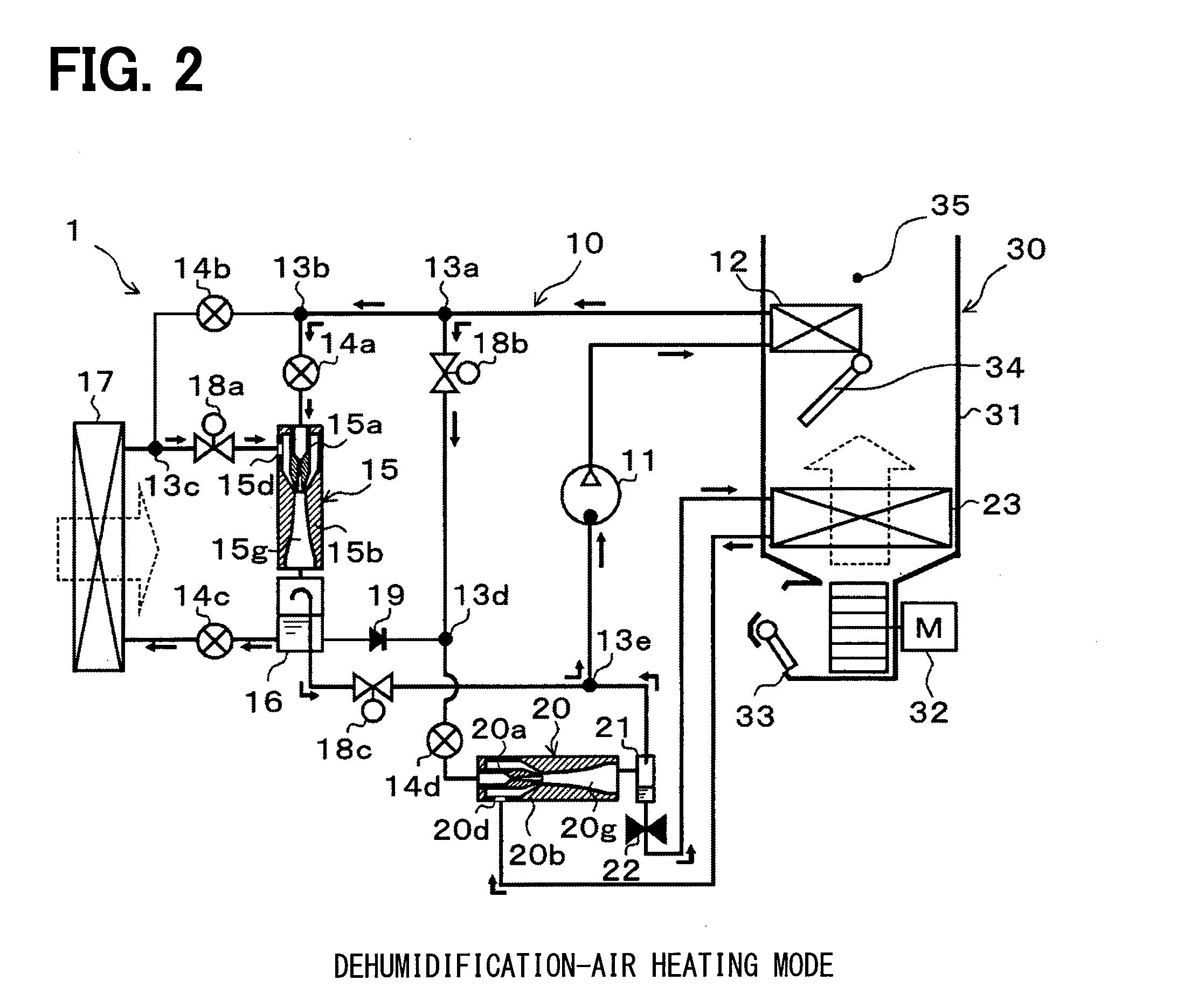
[0060]The refrigeration cycle apparatus 10 can be configured to perform switching among a refrigerant circuit in an air cooling mode of cooling the vehicle interior by cooling the air (see FIG. 1); a refrigerant circuit in a weak dehumidification-air heating mode of dehumidifying and heating the vehicle interior by reheating the air cooled and dehumidified (see FIG. 1); a refrigerant circuit in a dehumidification-air heating mode o...

second embodiment

[0229]As shown in the entire configuration diagram of FIG. 12, in a second embodiment, the cooling side ejector 20, the cooling side gas-liquid separator 21, and the fixed throttle 22 of the refrigeration cycle apparatus 10 are removed from the structure of the first embodiment, while the outlet side of the fourth flow rate adjustment valve 14d is connected to the refrigerant inlet side of the interior evaporator 23, and the refrigerant outlet side of the interior evaporator 23 is connected to the fifth three-way joint 13e by way of example.

[0230]That is, in the refrigeration cycle apparatus 10, the fourth flow rate adjustment valve 14d configures the cooling side decompressor. The structures of other components of the refrigeration cycle apparatus 10 except for the above points are the same as those of the first embodiment. Referring to FIG. 12, the same or equivalent parts as those described in the first embodiment are designated by the same reference numerals. The same goes for t...

third embodiment

[0243]In a third embodiment, as shown in the entire configuration diagram of FIG. 13, an auxiliary heating bypass passage 24 that guides the refrigerant discharged from the compressor 11 to the refrigerant inlet side of the interior evaporator 23, and a fourth opening / closing valve 18d for opening / closing the auxiliary heating bypass passage 24 are added to the refrigeration cycle apparatus 10 of the first embodiment. Further, instead of the fixed throttle 22, a fifth flow rate adjustment valve 14e is used.

[0244]The refrigeration cycle apparatus 10 of the third embodiment allows the fourth opening / closing valve 18d to open the auxiliary heating bypass passage 24, thereby performing switching to a refrigerant circuit in a strong air heating mode of performing air heating of the vehicle interior by heating air with a higher heating capacity than that in the air heating mode, in addition to other refrigerant circuits in the respective operation modes described in the first embodiment. ...


PUM


Abstract

In a dehumidification-air heating mode, a refrigerant circuit is configured such that a refrigerant outlet side of an exterior heat exchanger communicates with a heating side refrigerant suction port of a heating side ejector as a refrigerant decompression means, and that a refrigerant inlet side of an interior evaporator communicates with an outlet side of a heating side diffuser of the heating side ejector. A refrigerant evaporation temperature in the exterior heat exchanger is set lower than that of the interior evaporator by a pressurizing effect of the heating side ejector. Thus, the amount of heat absorption by the refrigerant at the exterior heat exchanger is increased to improve the heating capacity of the air in an interior condenser.

Description

CROSS REFERENCE TO RELATED APPLICATION[0001]The application is based on Japanese Patent Applications No. 2012-252475 filed on Nov. 16, 2012, No. 2013-055161 filed on Mar. 18, 2013, and No. 2013-127581 filed on Jun. 18, 2013, the contents of which are incorporated herein by reference in its entirety.FIELD OF THE INVENTION[0002]The present disclosure relates to a refrigeration cycle apparatus that is applied to an air conditioner so as to adjust the temperature of air to be blown into a space to be air-conditioned.BACKGROUND ART[0003]In the related art, Patent Document 1 discloses an evaporation compression refrigeration cycle apparatus that is applied to an air conditioner to adjust the temperature of air to be blown into a space to be air-conditioned. The refrigeration cycle apparatus disclosed in Patent Document 1 includes a refrigerant circuit switch for switching a refrigerant circuit for circulation of the refrigerant. The refrigeration cycle apparatus can be configured to perfo...

Claims


Application Information

Patent Timeline
Patent Type & Authority Applications(United States)
IPC IPC(8): F25B29/00
CPCF25B29/003F25B1/00F25B43/02F25B41/00F25B2341/0011F25B2341/0015B60H1/00921B60H2001/3298
Inventor AWA, RYOKONISHIJIMA, HARUYUKITAKANO, YOSHIAKIYAMADA, ETSUHISAITOH, SATOSHIKAYANO, KENTA
Owner DENSO CORP
Why Eureka
Try Eureka