Distance measuring method and equipment using optical signal

Active Publication Date: 2015-10-22
KIM TAE MIN
View PDF2 Cites 15 Cited by
  • Summary
  • Abstract
  • Description
  • Claims
  • Application Information

AI Technical Summary

Problems solved by technology

A LIDAR sensor system has basically several components including laser source, laser detector, signal collector and processor, and data transmitter/receiver, though

Method used


Image

  • Distance measuring method and equipment using optical signal
  • Distance measuring method and equipment using optical signal
  • Distance measuring method and equipment using optical signal

Examples


first embodiment

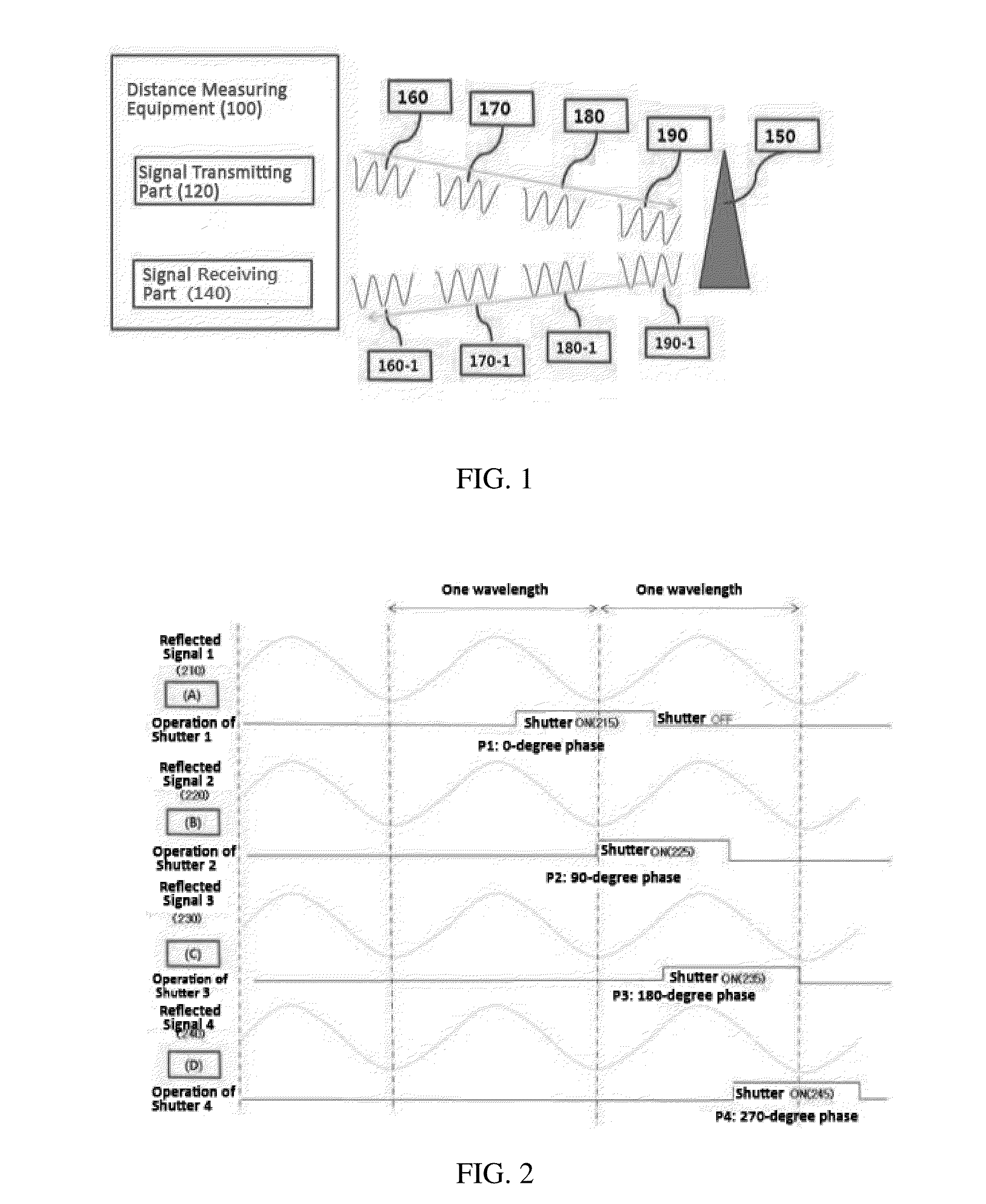
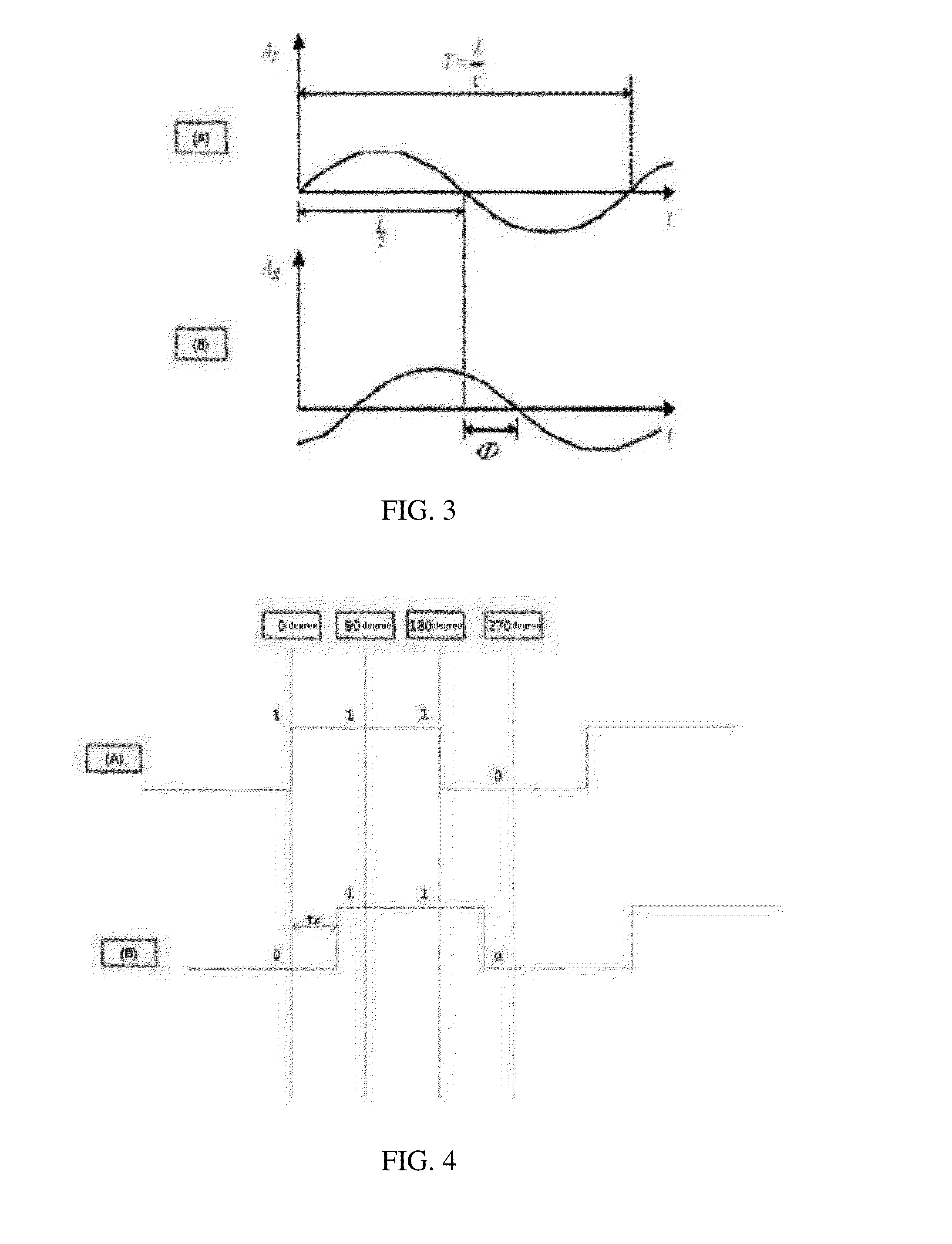
[0016]In order to achieve the first purpose of the present invention, distance measuring method using the phase difference of optical signal according to the present invention consists of a stage that receives multiple signals of same frequency and amplitude reflected from a target of measurement at different phases through the operation of the shutter, a stage that calculates the phase difference between transmitting and receiving signals based on said multiple signals received at said different phases, and a stage that calculates the distance between said target of measurement and a distance measuring equipment based on said phase difference.

[0017]Said stage that receives multiple signals reflected from said target of measurement at different phases through the operation of the shutter may consist of a stage that receives Signal 1 reflected from said target of measurement through the operation of Shutter 1 at Phase 1, a stage that receives Signal 2 reflected from said target of me...

second embodiment

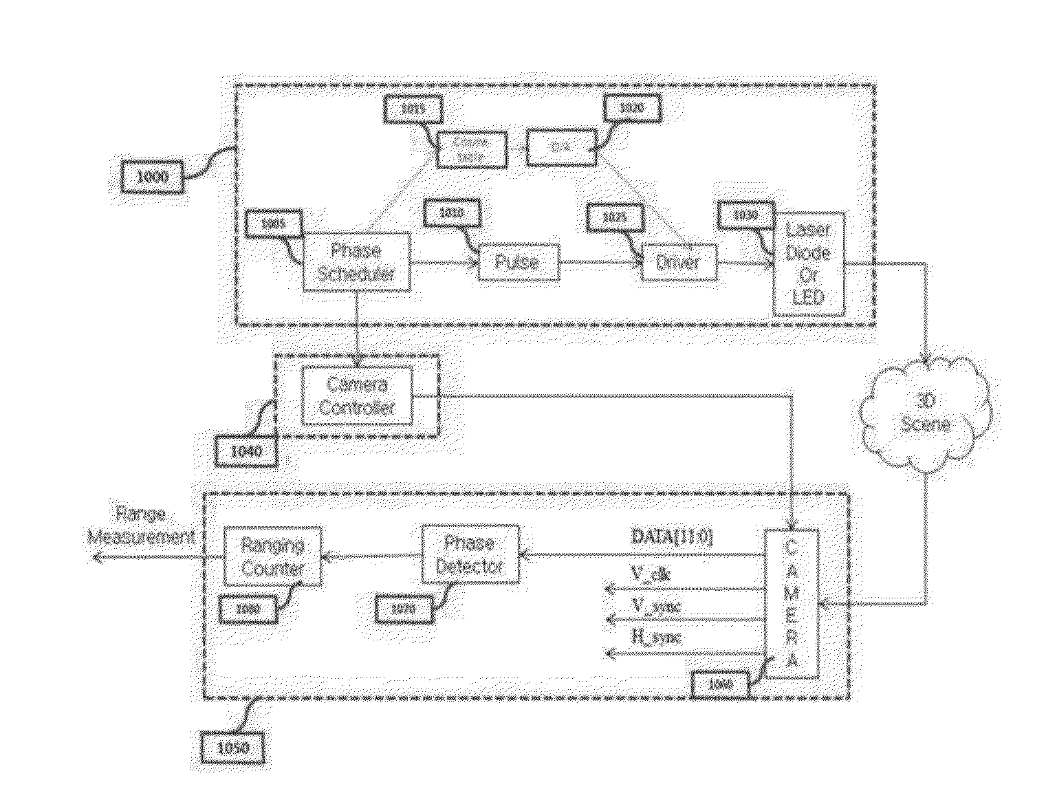
[0022]In order to achieve the second purpose of the present invention, distance measuring equipment using the phase difference of optical signal according to the present invention consists of a signal transmitter which transmits multiple signals of same frequency and amplitude, a signal receiving part which receives said multiple signals reflected from a target of measurement at different phases, and a control part which calculates the phase difference between transmitting and receiving signals based on said multiple signals received at different phases and calculates the distance between said target of measurement and distance measuring equipment based on said phase difference.

[0023]Said signal receiving part may be embodied so as to receive Signal 1 reflected from said target of measurement through the operation of Shutter 1 at Phase 1, Signal 2 reflected from said target of measurement through the operation of Shutter 2 at Phase 2, Signal 3 reflected from said target of measureme...


PUM


Abstract

The present invention relates to distance measuring method and equipment which consists of a stage that receives multiple signals reflected from the target of measuring through the operation of the shutter, a stage that calculates the phase difference between transmitting and receiving signals based on said multiple signals received at said different phases, and a stage that calculates the distance between said target of measurement and a distance measuring equipment based on said phase difference, and said multiple signals may be of same frequency and amplitude. Therefore, the phase difference between transmitting and receiving signals can be determined accurately and the distance to the objects can be accurately recognized.

Description

TECHNICAL FIELD[0001]The present invention relates to distance measuring method and equipment. More particularly, the present invention relates to distance measuring method and equipment using optical signal.DESCRIPTION OF RELATED ART[0002]A LIDAR (light detection and ranging) sensor is a device designed to detect a distance to a target, the direction, speed, temperature, material distribution, and concentration of the target by illuminating it with a laser and analyzing the reflected light.[0003]Taking advantages of the laser which can generate pulses of high energy density and short cycle or square wave signals, a LIDAR sensor is used to get more accurate measurement of properties in the air and distance.[0004]A LIDAR sensing technology was first attempted in 1930s to analyze the density in the upper air through the scattering strength of a searchlight but a full-fledged development of it was possible only after the invention of the laser in 1960s. Since 1970s, together with a con...

Claims


Application Information

Patent Timeline
IPC IPC(8): G01S7/486G01S17/10G01S7/4915G01S17/18G01S17/26G01S17/931
CPCG01S17/102G01S7/4868G01S17/36G01S7/4915G01S17/18G01S17/931G01S17/08G01S17/26
Inventor KIM, TAE MIN
Owner KIM TAE MIN
Why Eureka
Try Eureka