

Motor drive
- Summary
- Abstract
- Description
- Claims
- Application Information
AI Technical Summary
Benefits of technology
Problems solved by technology
Method used
Image

Examples
embodiment 1
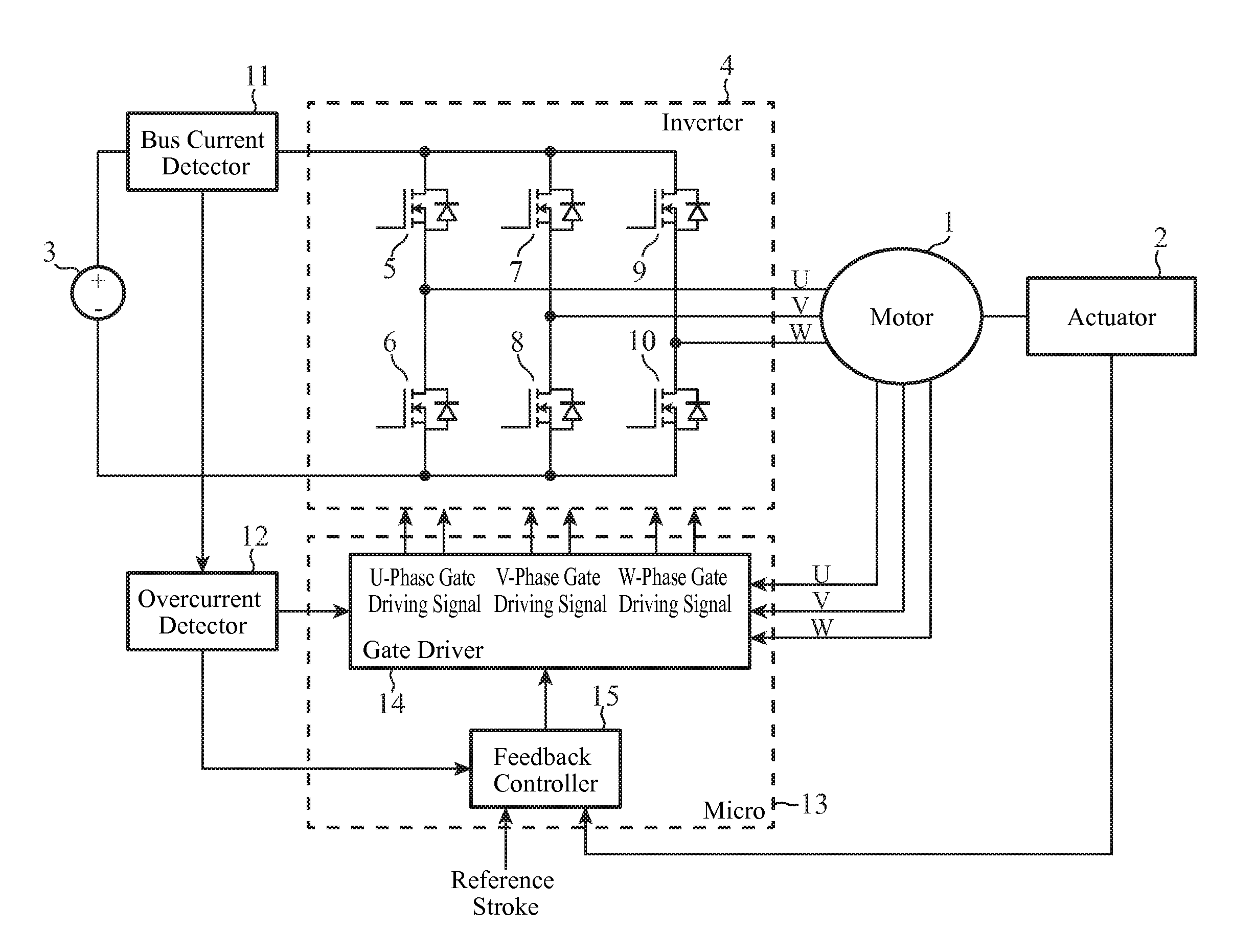
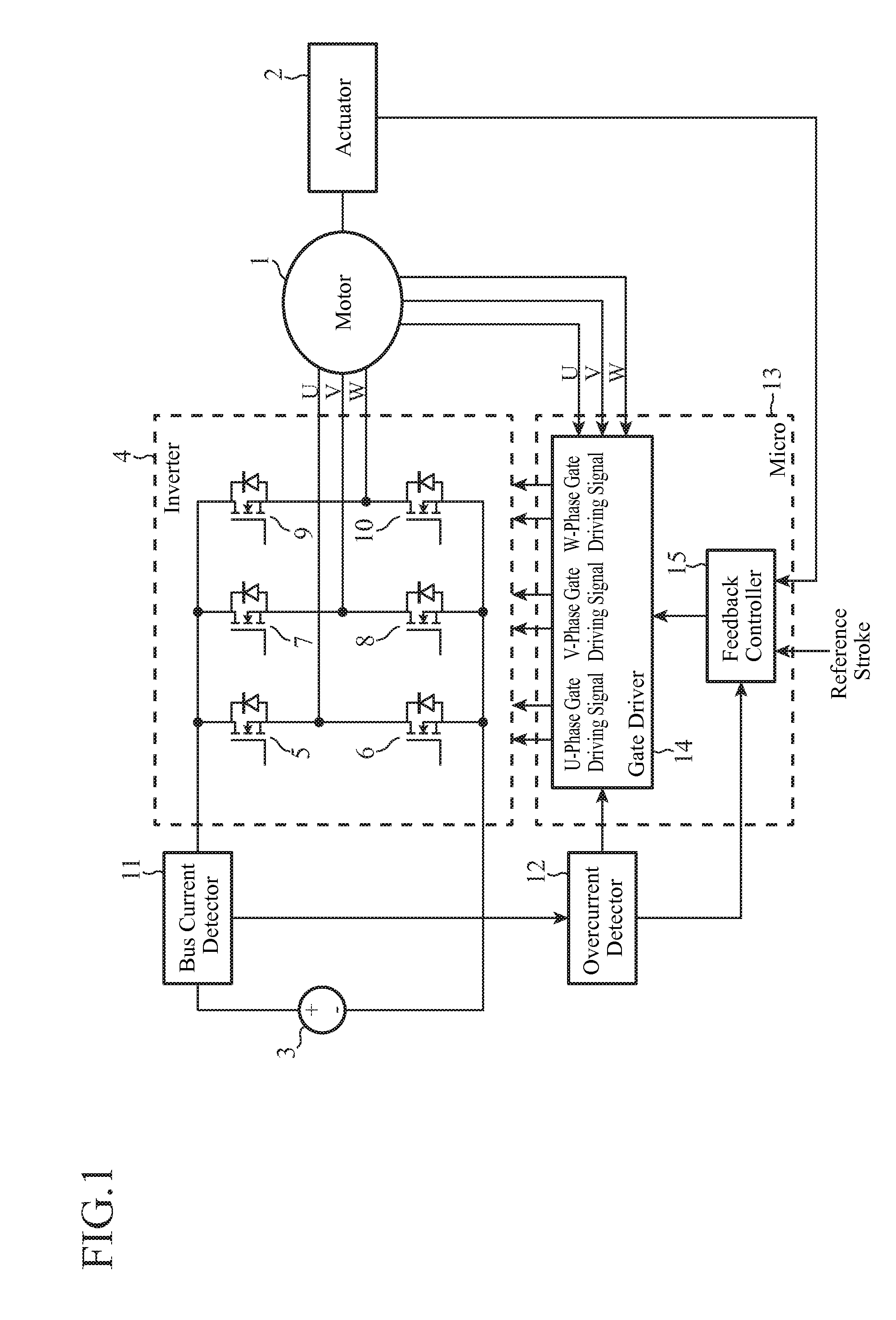
[0035]As shown in FIG. 1, a motor drive of the present embodiment 1 operates an actuator 2 by driving a motor (brushless motor) 1 with the AC output of a 3-phase inverter 4. A microcomputer (referred to as “micro” from now on) 13 controls the power supply from a DC power supply 3 to the motor 1 by controlling the gate driving signals of switching elements 5-10 constituting a 3-phase bridge, thereby controlling the motor 1 at a desired rotational state. Incidentally, although the switching elements 5-10 are denoted by a symbol of a MOS-FET, other switching elements such as an IGBT are also possible.
[0036]The magnitude of the bus current of the motor 1 is always observed with a bus current detector 11, and is supplied to an overcurrent detector 12. In FIG. 1, although the bus current detector 11 is configured to detect the positive side current of the DC power supply 3 as the bus current, it can be configured so as to detect the negative side GND current. The overcurrent detector 12 c...
embodiment 2
[0070]The motor drive of the embodiment 1 does not consider the rotation of the motor 1 at a PWM control restart. Even so, when restarting the PWM control from a stationary or low speed state, it can restart the PWM control without any trouble. However, when starting the PWM control during the rotation of the motor 1, an overcurrent is detected as designated by 93 of FIG. 6 because of the counter electromotive force, which brings about a power supply incapable state again.
[0071]Here, the magnitude of the bus current will be described when the short-circuit braking is terminated and the PWM control is restarted during the rotation of the motor 1.
[0072]FIG. 10(a) shows a waveform of the U-phase terminal voltage of the motor 1; FIG. 10(b) shows a waveform of the V-phase terminal voltage; and FIG. 10(c) shows a waveform of the W-phase terminal voltage. In each graph, the vertical axis represents voltage and the horizontal axis represents time. FIG. 10(d) shows waveforms of the individua...
embodiment 3
[0090]Since the motor drive of an embodiment 3 has the same configuration as the motor drive shown in FIG. 11 from the point of view of the drawing, it will be described with reference to FIG. 11.
[0091]FIG. 14 is a graph illustrating speed thresholds the duty ratio limiter 17 of the present embodiment 3 uses, in which the vertical axis represents duty ratio and the horizontal axis represents rotational speed. The positive and negative of the duty ratio represent driving directions, and the positive and negative of the rotational speed represent the rotational directions of the rotor.
[0092]The speed threshold ωa is assumed to be the rotational speed at which the current flowing through the bus equals the bus current tolerance when the rotational direction is forward and the limited duty ratio command value is 1. The speed threshold ωb is assumed to be the rotational speed at which the current flowing through each phase coil equals the bus current tolerance when the rotational directi...
PUM
 Abstract
Description
Claims
Application Information