
Isolation floatation chamber

a technology of isolation chamber and floatation chamber, which is applied in the direction of treatment room, multi-stage water/sewage treatment, treatment involving filtration, etc., can solve the problems of inability of operator or public health authority to determine correct measurement, inability to accurately measure water in isolation chamber, and inability to dosing blindly

Active Publication Date: 2015-10-29
HOEFLER CRAIG
View PDF12 Cites 11 Cited by
  • Summary
  • Abstract
  • Description
  • Claims
  • Application Information

AI Technical Summary

Benefits of technology

The patent describes a better way to disinfect a chamber using UV radiation and ozone injection. Ozone is a short-lived gas that doesn't produce any toxic byproducts. The amount of dissolved ozone can be accurately monitored using a sensor system. The technical effect of this method is that it provides a more effective and safe way to disinfect chambers.

Problems solved by technology

As with swimming pools and other recreational water facilities, the water in an isolation chamber is subject to undesirable contaminants introduced by the users and environment.
In a magnesium sulfate solution one cannot accurately monitor the chemical residual, making it impossible for either the operator or public health authority to determine correct measurement of disinfecting chemicals, resulting in blind dosing.
Exposure to chloramines can cause respiratory problems, rashes and other skin conditions, eye irritation, digestive disorders, and other health issues.
In addition, chloramines also produce an irritating odor which is particularly undesirable for isolation chambers, where the desired goal is to isolate the user as much as possible from external stimuli.

Method used


Image

  • Isolation floatation chamber
  • Isolation floatation chamber
  • Isolation floatation chamber

Examples


Embodiment Construction

[0016]Illustrative embodiments and exemplary applications will now be described with reference to the accompanying drawings to disclose the advantageous teachings of the present invention.

[0017]While the present invention is described herein with reference to illustrative embodiments for particular applications, it should be understood that the invention is not limited thereto. Those having ordinary skill in the art and access to the teachings provided herein will recognize additional modifications, applications, and embodiments within the scope thereof and additional fields in which the present invention would be of significant utility.

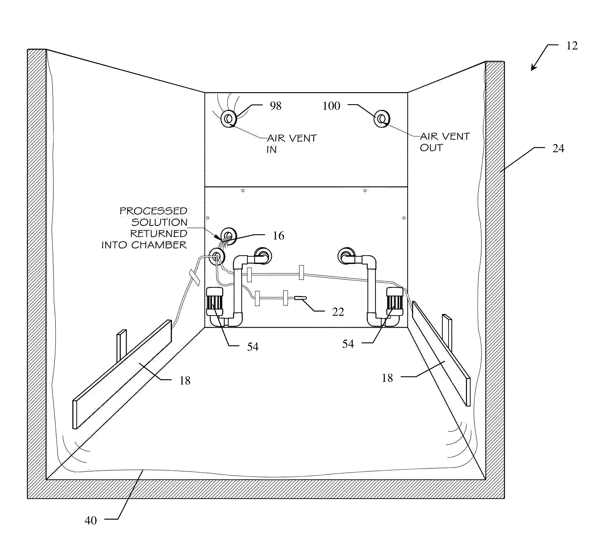
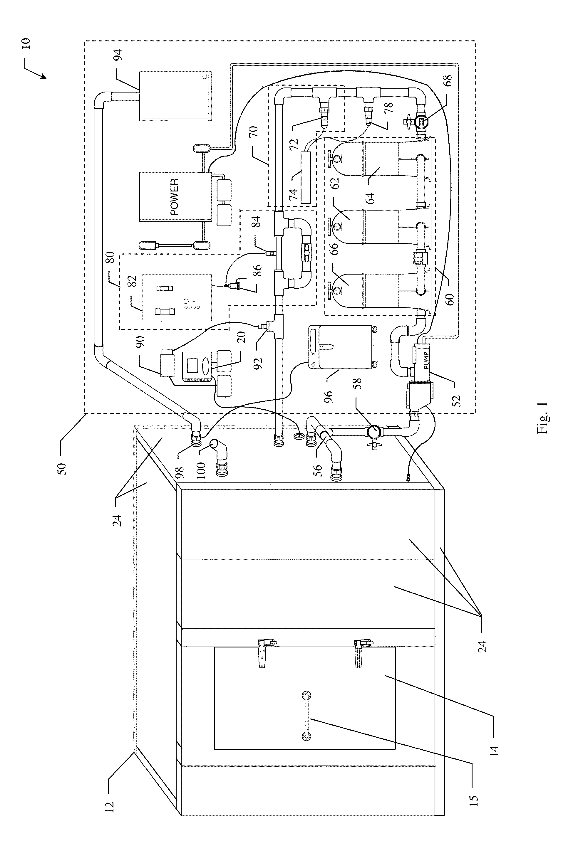
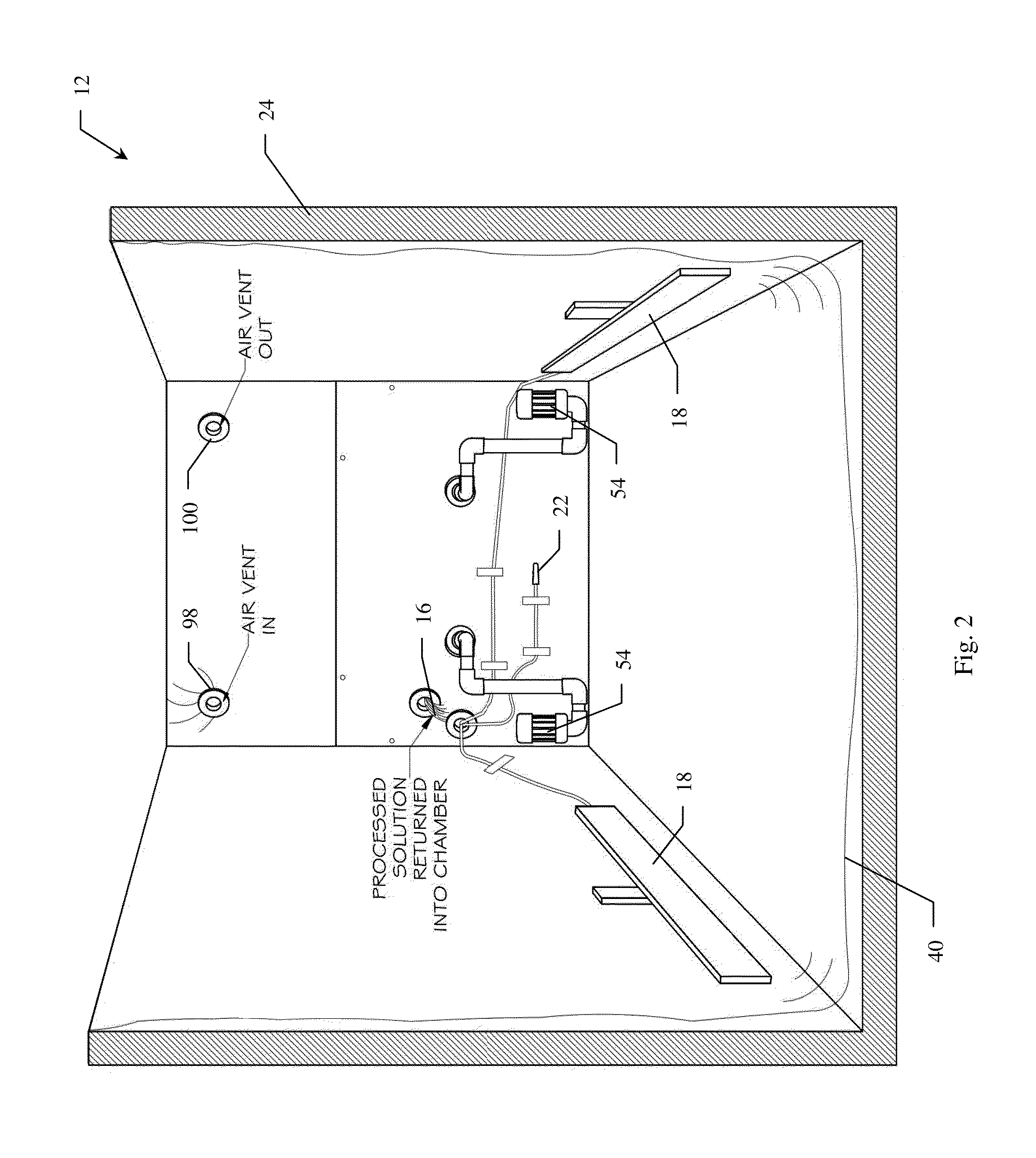
[0018]The present invention provides a novel isolation chamber and disinfection system designed for commercial usage. Unlike conventional isolation tanks, the inventive system does not rely on chemical disinfectants. Instead, it uses a combination of UV (ultraviolet) radiation and ozone to disinfect the floatation solution. In accordance with the pre...


PUM


Abstract

An isolation chamber and disinfection system. The novel system includes an enclosure for providing a sturdy, lightless and soundproofed environment and for containing a solution for supporting a user in a state of floatation; a disinfection system for disinfecting the solution, the disinfection system including an ultraviolet disinfection system and an ozone injection system; and a pump for removing the solution from the enclosure and circulating it through the disinfection system at a predetermined flow rate. The enclosure is formed from interlocking, foam-insulated panels and lined with a potable liner that holds the solution. In relationship to the isolation chamber, in accordance with the present teachings, an improved method of disinfection is taught using UV radiation with ozone injection. Ozone has a short half-life and leaves substantially no toxic byproducts. Verification of disinfection can be accomplished by monitoring the dissolved ozone, which can be determined accurately utilizing a dissolved ozone sensor system.

Description

REFERENCE TO RELATED APPLICATION[0001]This application claims priority from a Provisional Application entitled Isolation Floatation Chamber, filed Apr. 30, 2013, by C. Hoefler, application No. 61 / 817,373.BACKGROUND OF THE INVENTION[0002]1. Field of the Invention[0003]The present invention relates to isolation chambers. More specifically, the present invention relates to systems and methods for disinfecting floatation tanks.[0004]2. Description of the Related Art[0005]An isolation chamber, or floatation tank, is a dark, soundproofed enclosure containing a layer of salt water upon which a user floats, typically for relaxation or meditation purposes. The chamber is designed to isolate the user from external stimuli such as light, sound, smell, and, in particular, gravity. Epsom salt is usually added to the water in the isolation tank to increase the density of the solution such that the user floats comfortably near the surface with the face above the water. The buoyancy created by this...

Claims


Application Information

Patent Timeline
IPC IPC(8): A61M21/00A61L2/10A61L2/18
CPCA61M21/0094A61M2021/0066A61L2/10A61L2/183A61L2/022A61L2202/122A61L2202/15A61L2209/14A61M21/02A61M2021/0022A61M2205/11A61M2205/3368A61M2209/10C02F1/001C02F1/32C02F1/444C02F1/78C02F9/00C02F2103/42C02F2201/326C02F2201/782A61L2/00A61L9/00
Inventor HOEFLER, CRAIG
Owner HOEFLER CRAIG
Learn More