Mid-Cycle Fuel Injection Strategies

Active Publication Date: 2015-10-29
WESTPORT FUEL SYST CANADA INC
View PDF2 Cites 15 Cited by
  • Summary
  • Abstract
  • Description
  • Claims
  • Application Information

AI Technical Summary

Benefits of technology

[0023]The engine can employ conventional timing for opening and closing the intake valve but different timings for opening and closing the intake valve can be employed, particularly if the engine has a variable valve timing system so that different timings for opening and closing the intake valve can be used for different operating modes. For example, in some embodiments, the intake valve is operable

Problems solved by technology

While this method does not have the advantages of mixing the gaseous fuel with the charge as it is inducted into the combustion chamber, this embodiment of the method does reduces the compl

Method used


Image

  • Mid-Cycle Fuel Injection Strategies
  • Mid-Cycle Fuel Injection Strategies
  • Mid-Cycle Fuel Injection Strategies

Examples


first embodiment

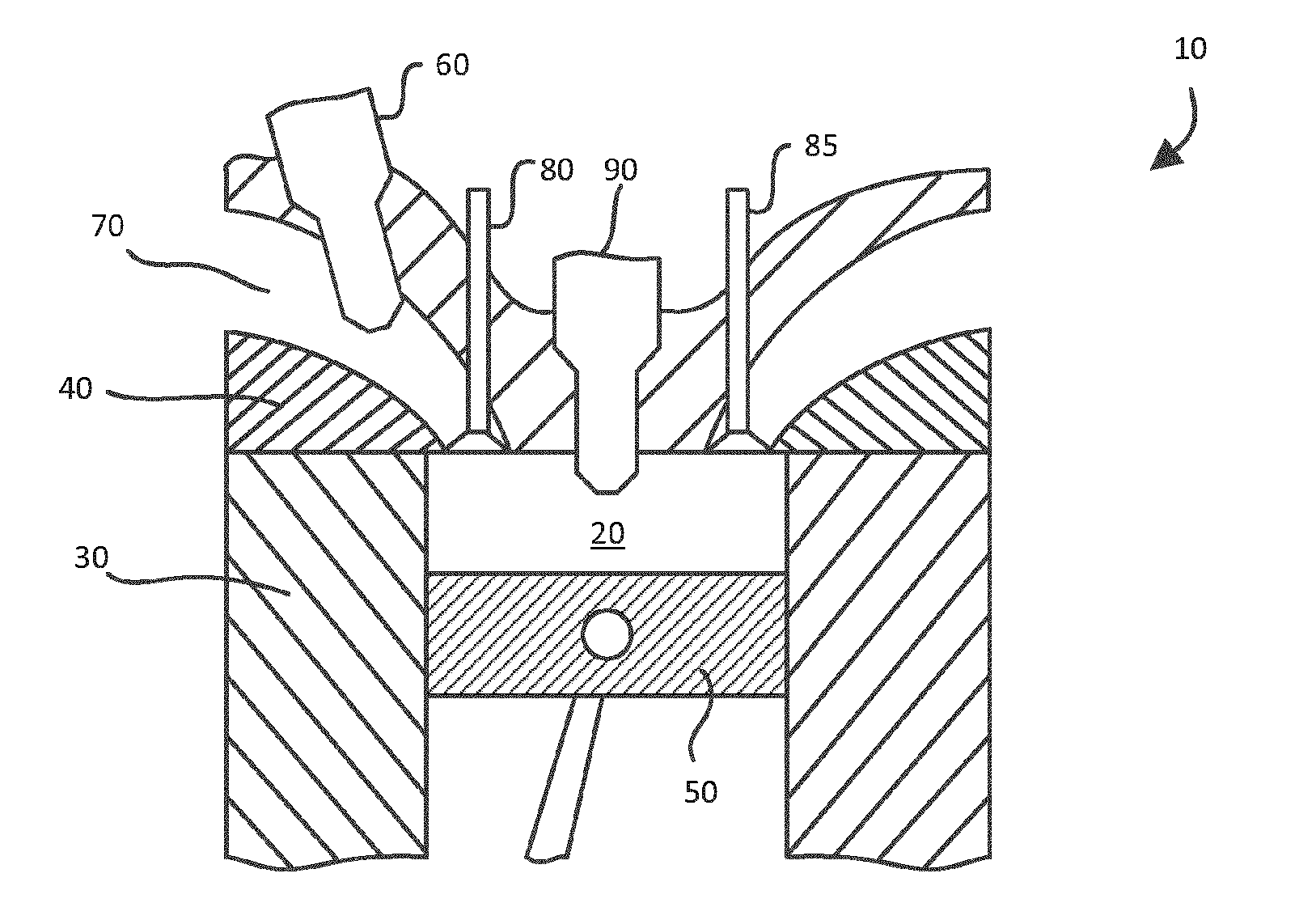
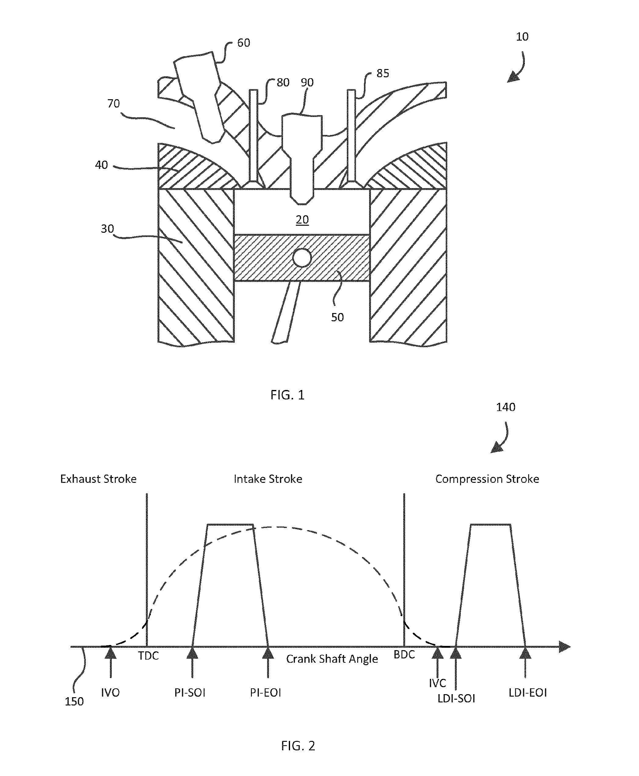
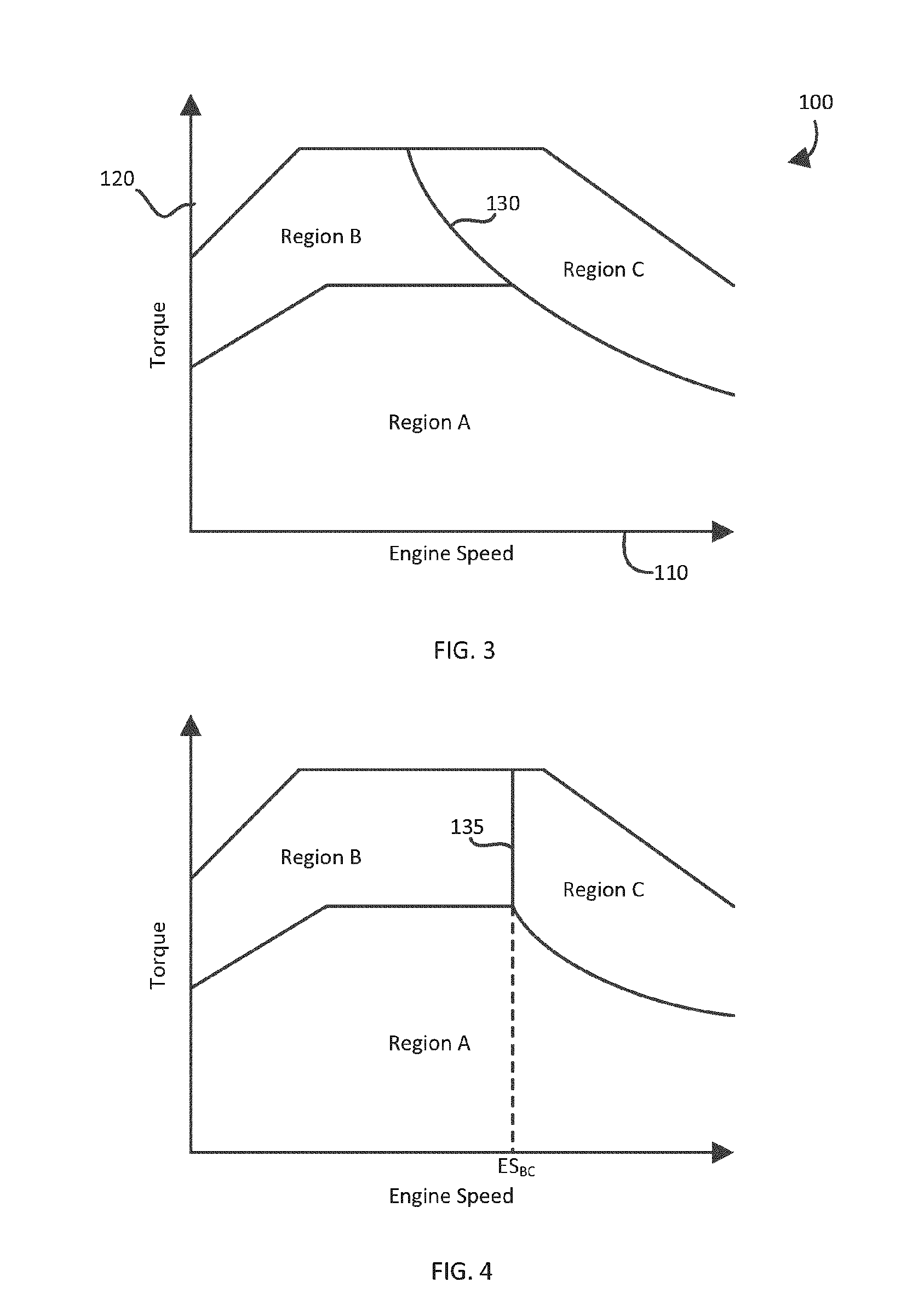
[0031]a technique for introducing gaseous fuel to an internal combustion engine is illustrated in FIGS. 1, 2, 3 and 4. With reference to FIG. 1, engine 10 comprises combustion chamber 20, which in this example is defined by cylinder wall 30, cylinder head 40 and piston 50. Only one cylinder is shown in FIG. 1 although engine 10 normally comprises two or more cylinders, and the technique disclosed herein applies to engines having one or more cylinders. Port fuel injector 60 introduces gaseous fuel to intake manifold 70 upstream of intake valve 80 such that a charge of at least air and gaseous fuel is sucked into combustion chamber 20. Direct fuel injector 90 directly introduces gaseous fuel to combustion chamber 20. In the present embodiment engine 10 comprises a throttle (not shown) employed to control the intake of air into combustion chamber 20. In other embodiments engine 10 can comprise liquid fuel injectors that introduce a liquid fuel, such as gasoline, directly into combustio...

second embodiment

[0041]Referring now to FIGS. 5 and 6, and first to FIG. 5, a technique for introducing gaseous fuel to an internal combustion engine is illustrated where like parts to the previous embodiment have like reference numerals and may not be described in detail, if at all. Direct fuel injector 91 introduces gaseous fuel to combustion chamber 20. Engine 11 in the present embodiment is operated, similar to the previous embodiment, according to at least one of engine maps 100 of FIGS. 3 and 4. Engine cycle event line event line 141 of FIG. 6 is similar to that of FIG. 2, and the fueling strategies in regions A, B and C of the present embodiment are similar to the previous embodiment. Injector 91 can function to introduce gaseous fuel during the intake stroke and alternatively, or in addition to, during the compression stroke. When introducing fuel during the intake stroke, direct fuel injector 91 starts introducing gaseous fuel at early direct injection-start of injection (EDI-SOI). Early di...

third embodiment

[0044]Referring now to FIG. 7, a technique for introducing gaseous fuel to an internal combustion engine is illustrated where like parts to the previous embodiments have like reference numerals and may not be described in detail, if at all. Engine cycle event line 142 can be employed with engine 10 in FIG. 1 and with engine 11 in FIG. 5. When used with engine 10, PI-SOI and PI-EOI are employed, and when used with engine 11, EDI-SOI and EDI-EOI are employed, according to the fueling strategies discussed previously. Intake valve closed (IVC) occurs during the intake stroke before bottom dead center (BDC) in this embodiment. Closing intake valve 80 before BDC results in an over-expanded cycle where the effective expansion stroke is longer than the effective compression stroke. In a normally aspirated engine this would result in a reduction of power because less air (oxygen) is introduced to combustion chamber 20 during the intake stroke. To offset this power reduction, a turbo-charger ...


PUM


Abstract

A method and apparatus are disclosed for introducing a gaseous fuel into a combustion chamber of an internal combustion engine. The method includes dividing the engine map into three distinct operating regions, with different operating modes in each region. When the engine is operating in a low load region, gaseous fuel is introduced to the combustion chamber during an intake stroke before an intake valve associated with the combustion chamber closes. When the engine is operating in a high load low-speed region, gaseous fuel is directly injected into the combustion chamber during a compression stroke after the intake valve is closed. When the engine is operating in a high load high-speed region, a split injection strategy is employed with a first portion of the gaseous fuel introduced into the charge before the intake valve closes and a second portion being injected after the intake valve is closed.

Description

CROSS-REFERENCE TO RELATED APPLICATIONS[0001]This application is a continuation of International Application No. PCT / CA2013 / 050956 having a filing date of Dec. 12, 2013, entitled “Mid-Cycle Fuel Injection Strategies”, which claimed priority benefits from Canadian patent application No. 2,799,952 filed on Dec. 20, 2012. The '956 international application is hereby incorporated by reference herein in its entirety.FIELD OF THE INVENTION[0002]The present application relates to techniques of introducing gaseous fuel to an internal combustion engine according to fueling regions in an engine map determined as a function of engine operating conditions.BACKGROUND OF THE INVENTION[0003]Alternative fuels such as natural gas are being adopted by engine manufacturers in so called dual fuel, bi-fuel and flex-fueled engines. Dual fuel engines are fueled with more than one fuel type simultaneously, for example engines that consume natural gas as a main fuel and diesel as a pilot ignition fuel. Bi-f...

Claims


Application Information

Patent Timeline
IPC IPC(8): F02D41/00F02M21/02F02D13/02F02D41/30
CPCF02D41/0027F02D41/3094F02M21/0215F02D13/0223F02M21/0275F02M21/0284F02M21/0278F02D41/402F02D19/024F02D13/0234F02D13/0269Y02T10/12Y02T10/40Y02T10/30F02D19/0642F02D19/0647F02D41/0025
Inventor DUNN, MARK E.WELCH, ALAN B.
Owner WESTPORT FUEL SYST CANADA INC
Why Eureka
Try Eureka