
Traffic control system and method of use

Inactive Publication Date: 2015-10-29
HAWS CORP
View PDF9 Cites 36 Cited by
  • Summary
  • Abstract
  • Description
  • Claims
  • Application Information

AI Technical Summary

Benefits of technology

The invention is a traffic control system that uses centralized mechanisms to control traffic signals at intersections or trafficways. This system can detect the presence of vehicles and determine their type and destination, allowing for preemptive traffic signaling instructions to be sent to intersections. The system can also include boundary detection mechanisms to track vehicles and direct traffic accordingly. This centralized approach reduces errors, risks, and intelligence limitations associated with request-based systems, resulting in safer and more efficient operations.

Problems solved by technology

Such conventional systems generally failed to address the dynamic nature of traffic flow, such as changes to traffic volume for a given trafficway over time, resulting in traffic backups and general inefficiency.
Such approaches have exhibited limited effectiveness in increasing traffic flow efficiencies particularly due to technical limitations such as fixed signal patterns, execution of simple timing resets, non-specific vehicle presence detection (e.g., below-pavement weight sensors), and the like.
Further, these historical technologies generally were not sophisticated enough to accommodate dynamic and contextually-specific purposes of particular areas or trafficways, such as, for example, enabling certain types of vehicles to proceed at certain times in order to achieve certain ends.
The '984 system is relatively complex, involving multiple layers of request generation and forwarding, and requiring the vehicle to initiate TSP requests.
Reliance on vehicle issuance of TSP requests in combination with central system forwarding of requests, however, can result in an increased risk of failure of the vehicle-based system to issue, process, and execute a TSP request when necessary.
This can be particularly problematic, and even life threatening, at certain types of intersections such as those at mining sites where haul trucks with limited visibility, which can be enormous in size, seek to have the right of way through an intersection when desired or needed.
Stop and start cycles for haul trucks carrying heavy loads (e.g., 100-plus tons of ore, 240-plus tons of ore, etc.) can cause significant wear on vehicles and the trafficway, and can reduce overall fleet effectiveness.
For example, continued stopping and starting of such a haul truck fleet can result in the moving of less ore, burning of extra fuel, generation of higher maintenance costs, and reduction in equipment life.
Further, failure of a haul truck to stop properly at such an intersection can cause tremendous damage to other vehicles and their occupants.
Use of conventional TSP-based traffic event locating techniques, such as that described in the '984 patent, can be inadequate, particularly when utilized in industrial locations such as a mining site.
One drawback to TSP request models is they tend to operate within normal signal operation, modifying such operation in terms of resetting the normal signal cycle time.
Simple modifications such as this can be inadequate for accomplishing efficient management of site-specific traffic.
By generally employing simplified, request-based, control strategies, TSP-based traffic control systems typically fail to adequately account for the multiple factors relevant to determining the most efficient ordering and timing of intersection access and traversal that would otherwise further the unique purposes of the site.
Conventional traffic management solutions generally lack mechanisms to perform multi-factor analysis, weighting, or both such that various resource types can be efficiently utilized within a particular environment.
Failure to account for factors such as, for example, vehicle types, vehicle purposes, vehicle conditions, environmental conditions, and the relationships across various factors can reduce efficiency significantly and can work against the unique purpose of the site.
Developing a solution to the long-standing problem of achieving a lower sustainable operational cost while increasing production levels has been elusive.

Method used


Image

  • Traffic control system and method of use
  • Traffic control system and method of use
  • Traffic control system and method of use

Examples


Embodiment Construction

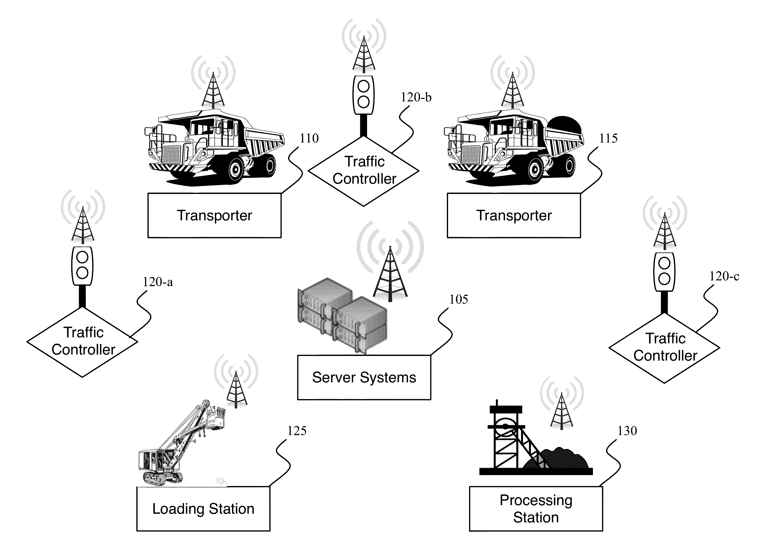
[0015]The applicants believe that they have discovered at least some of the issues and problems such as those noted above for prior systems such as the '984 system discussed previously. The applicants have therefore invented a traffic control system that can include, at least in part, centralized traffic flow control mechanisms, such as a centralized detection engine, preference ranking engine, decision engine, and boundary engine that, in combination in whole or in part, can control traffic signaling states across one or more intersection or trafficways at a site. Centralization of ranking and preemption determinations can reduce or eliminate the error, risk, and intelligence limitations associated with request-based systems, such as the TSP request-based system described in the '984 patent.

[0016]In some implementations, the system determines if a particular type of vehicle, such as a very large truck, has arrived at a distance from an intersection. Upon determining that the vehicl...


PUM


Abstract

An automated traffic control process and system providing automatic remote monitoring the locations of one or more remote vehicles, determining which vehicles fall within one or more preference categories, and if a vehicle in a particular preference category is detected as approaching a remote intersection, issuing a preemption instruction to a traffic signal controller for the remote intersection. Various other process and system features can include one or more among: monitoring numerous vehicles and intersections, vehicle location monitoring, categorization, and issuance of preemption instructions on a centralized computing system; safety or other condition assessment and control of issuance of signaling instructions accordingly; determination of whether one or more the traffic intersection signaling controller should be operating according to one among differing hierarchical condition categories, and issuance of instructions causing remote traffic signaling to lock in a particular state, such as, for example in a right of way state.

Description

CROSS-REFERENCE TO RELATED APPLICATIONS[0001]This application claims priority through: (i) the applicants' provisional application of the same title, Traffic Control System and Method of Use, filed Apr. 9, 2014, Application No. 61 / 977,530; (ii) applicants' provisional application of the same title, Traffic Control System and Method of Use, filed Aug. 6, 2014, Application No. 62 / 034,039; and (iii) the applicants' provisional application of the same title, Traffic Control System and Method of Use, filed (before this application was filed) on Apr. 9, 2015, Application No. 62 / 178,426, all of which provisional applications are hereby incorporated by reference in their entirety.COPYRIGHT NOTICE[0002]This patent document contains material subject to copyright protection. The copyright owner has no objection to the photocopy reproduction of the patent document or the patent disclosure in exactly the form it appears in the Patent and Trademark Office patent file or records, but otherwise res...

Claims


Application Information

Patent Timeline
IPC IPC(8): G08G1/015G08G1/095G08G1/087G08G1/017
CPCG08G1/015G08G1/087G08G1/095G08G1/017G08G1/081
Inventor SIMANOWSKI, ANDREASODDO, RYANTOLOTTI, JORDONMILLER, LAWRENCESTICHTER, KEVIN
Owner HAWS CORP
Learn More