Gas turbine engine fuel system

a fuel system and gas turbine engine technology, applied in the direction of liquid fuel engines, machines/engines, rotary/oscillating piston pump components, etc., can solve the problems of relatively inefficient voltage regulation, large volume and weight of power electronics units, and need cooling systems

Active Publication Date: 2015-11-05
ROLLS ROYCE PLC
View PDF4 Cites 12 Cited by
  • Summary
  • Abstract
  • Description
  • Claims
  • Application Information

AI Technical Summary

Benefits of technology

[0016]The main generator may comprise a generator control unit configured to control the voltage of power generated by the main AC generator. Consequently, a further form of speed control can be provided, which may provide further flexibility, and may provide redundancy.

Problems solved by technology

Both of these methods have disadvantages.
Power electronics units are relatively bulky and heavy, and may require cooling systems, particularly in view of the large electrical current required to provide the needed torque.
Voltage regulation is relatively inefficient, and has a limited range of output speeds for a given electrical AC input frequency.

Method used


Image

  • Gas turbine engine fuel system
  • Gas turbine engine fuel system
  • Gas turbine engine fuel system

Examples


Embodiment Construction

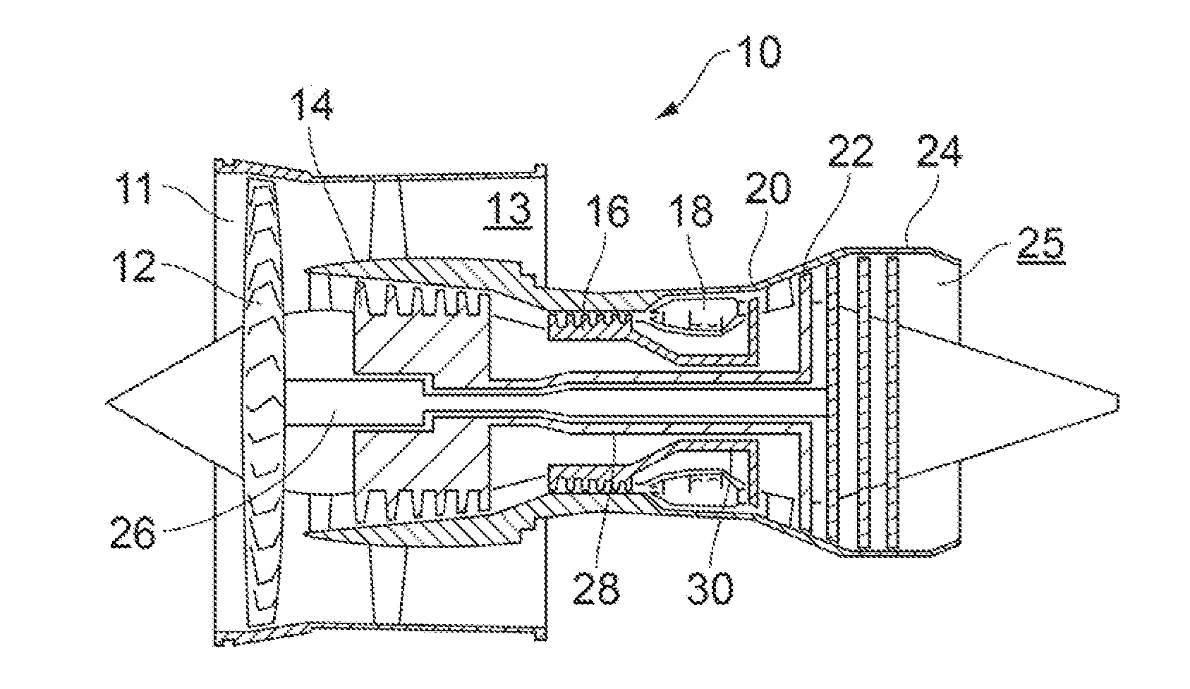
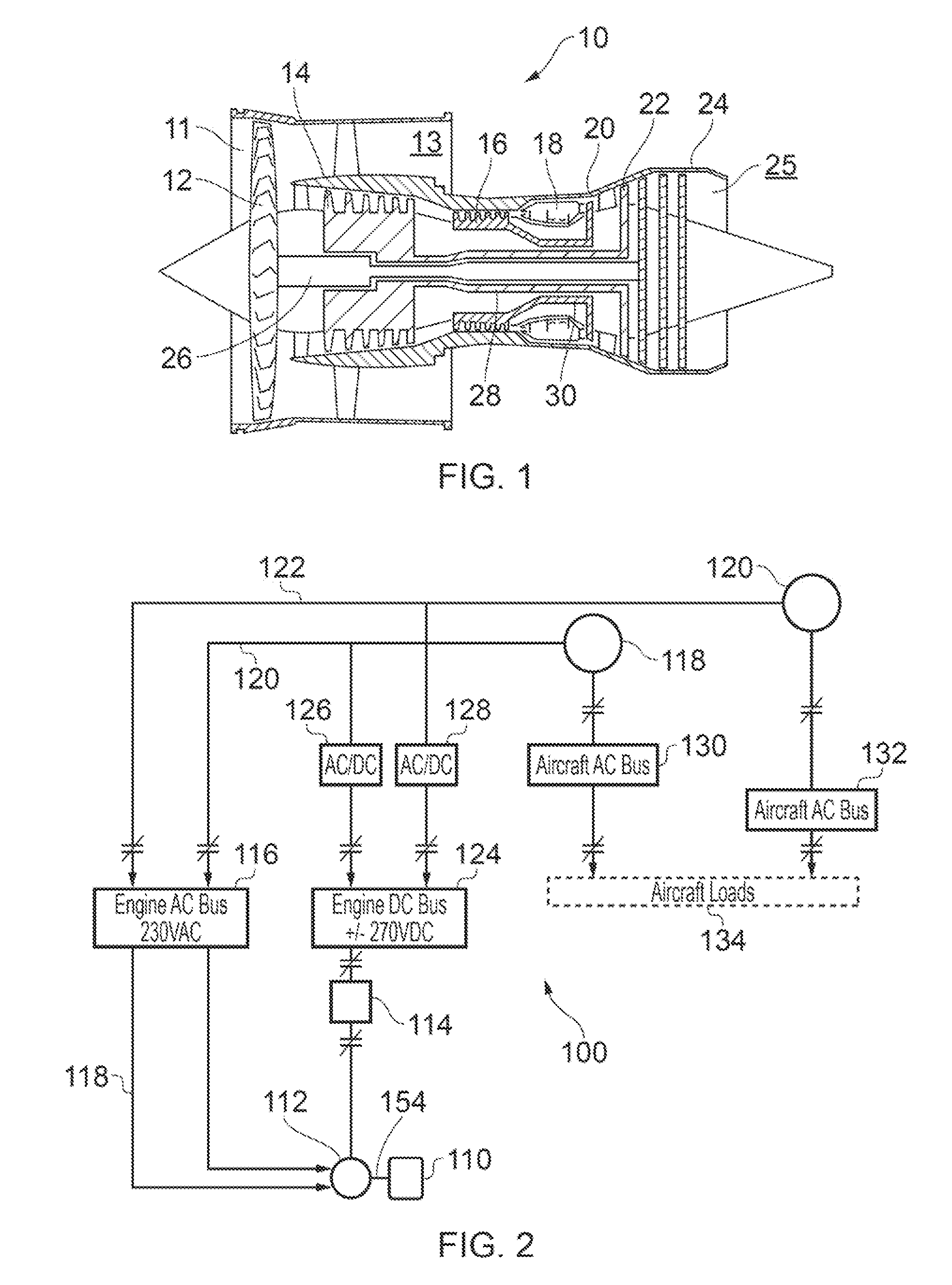
[0028]FIG. 1 shows a high-bypass gas turbine engine 10. The engine 10 comprises, in axial flow series, an air intake duct 11, an intake fan 12, a bypass duct 13, an intermediate pressure compressor 14, a high pressure compressor 16, a combustor 18, a high pressure turbine 20, an intermediate pressure turbine 22, a low pressure turbine 24 and an exhaust nozzle 25. The fan 12, compressors 14, 16 and turbines 20, 22, 24 all rotate about the major axis of the gas turbine engine 10 and so define the axial direction of gas turbine engine.

[0029]Air is drawn through the air intake duct 11 by the intake fan 12 where it is accelerated. A significant portion of the airflow is discharged through the bypass duct 13 generating a corresponding portion of the engine 10 thrust. The remainder is drawn through the intermediate pressure compressor 14 into what is termed the core of the engine 10 where the air is compressed. A further stage of compression takes place in the high pressure compressor 16 b...


PUM


Abstract

The present application discloses a fuel system for a gas turbine engine. The engine includes a main alternating current electrical generator driven by an engine shaft such that the electrical output frequency of the electrical generator varies in dependence on shaft rotational speed. The fuel system includes a variable flow fuel pump for providing a fuel flow to the engine, a frequency and/or voltage controller configured to provide electrical power having at least one of a predetermined output frequency and a predetermined voltage, and a variable speed electric motor configured to drive the fuel pump. The electric motor includes an induction motor having a stator and at least a first rotor, the stator having first and second sets of stator windings. Each set of stator windings is configured to impart a torque on the rotor in use.

Description

FIELD OF THE INVENTION[0001]The present invention relates to a fuel system for a gas turbine engine, and a gas turbine engine comprising a fuel system.BACKGROUND TO THE INVENTION[0002]FIG. 1 shows a high-bypass gas turbine engine 10. The engine 10 comprises, in axial flow series, an air intake duct 11, an intake fan 12, a bypass duct 13, an intermediate pressure compressor 14, a high pressure compressor 16, a combustor 18, a high pressure turbine 20, an intermediate pressure turbine 22, a low pressure turbine 24 and an exhaust nozzle 25. The fan 12, compressors 14, 16 and turbines 20, 22, 24 all rotate about the major axis of the gas turbine engine 10 and so define the axial direction of gas turbine engine.[0003]Air is drawn through the air intake duct 11 by the intake fan 12 where it is accelerated. A significant portion of the airflow is discharged through the bypass duct 13 generating a corresponding portion of the engine 10 thrust. The remainder is drawn through the intermediate...

Claims


Application Information

Patent Timeline
Patent Type & Authority Applications(United States)
IPC IPC(8): F02C9/30F02C6/00H02K16/02F04C15/00H02K17/12H02K3/46F02C7/22F04C2/08
CPCF02C9/30F02C7/22F02C6/00F04C2/08F04C15/008F05D2260/60H02K3/46H02K16/02F05D2220/32F05D2220/76H02K17/12F04C2210/1044F04C2240/403F04C2270/095F04C2270/105F05D2220/764F05D2270/03F05D2270/061F05D2270/07H02K3/28H02K16/00H02K2213/06H02K2213/09H02K2213/12
Inventor EDWARDS, HUW LLEWELYNHUSBAND, STEPHEN MARKCULLEN, JOHN JAMES ANTHONY
Owner ROLLS ROYCE PLC
Why Eureka
Try Eureka