Long base inclinometer with optical measurement

a technology of optical measurement and inclinometer, which is applied in the field of tiltmeter, can solve the problems of no commercially available array installation device, small deformation, and long-term instability of the tiltmeter, and achieve the effects of eliminating noise or thermal, electromagnetic, atmospheric, electromagnetic errors produced by the environment, and eliminating all common mode nois

Active Publication Date: 2015-11-05
CENT NAT DE LA RECHERCHE SCI +1
View PDF4 Cites 7 Cited by
  • Summary
  • Abstract
  • Description
  • Claims
  • Application Information

AI Technical Summary

Benefits of technology

[0026]Coupling the optical measuring devices to a single common light source advantageously makes it possible to eliminate all common mode noise. Coupling the optical measuring devices to a single common light source advantageously makes it possible to eliminate the wavelength drift inherent to each light source as well as noise or thermal, atmospheric, electromagnetic errors produced by the environment.
[0027]Moreover, in contrast to existing long baseline tiltmeters necessitating a plurality of light sources and optical and mechanical components at the level of each pot, thereby increasing the overall cost of said tiltmeters, the tiltmeter in accordance with the invention with a single remotely sited light source has a significantly reduced manufacturing cost.
[0028]Monitoring drift by a duplicated measurement and using a common light source also has an economic advantage. This makes it possible to use a stable light source costing at least 10 to 1...

Problems solved by technology

Between two earthquakes deformations exist but are very small and very slow.
At present there are no commercially available devices that can be installed in an array and are capable of producing a high-resolution measurement that is stable in the long term.
Such devices can be installed in bores and in arrays but p...

Method used


Image

  • Long base inclinometer with optical measurement
  • Long base inclinometer with optical measurement
  • Long base inclinometer with optical measurement

Examples


Embodiment Construction

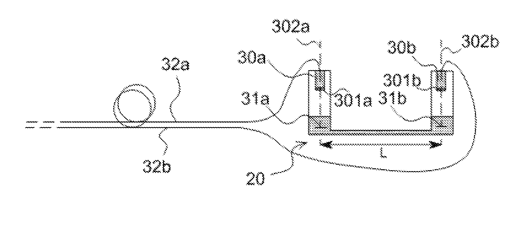
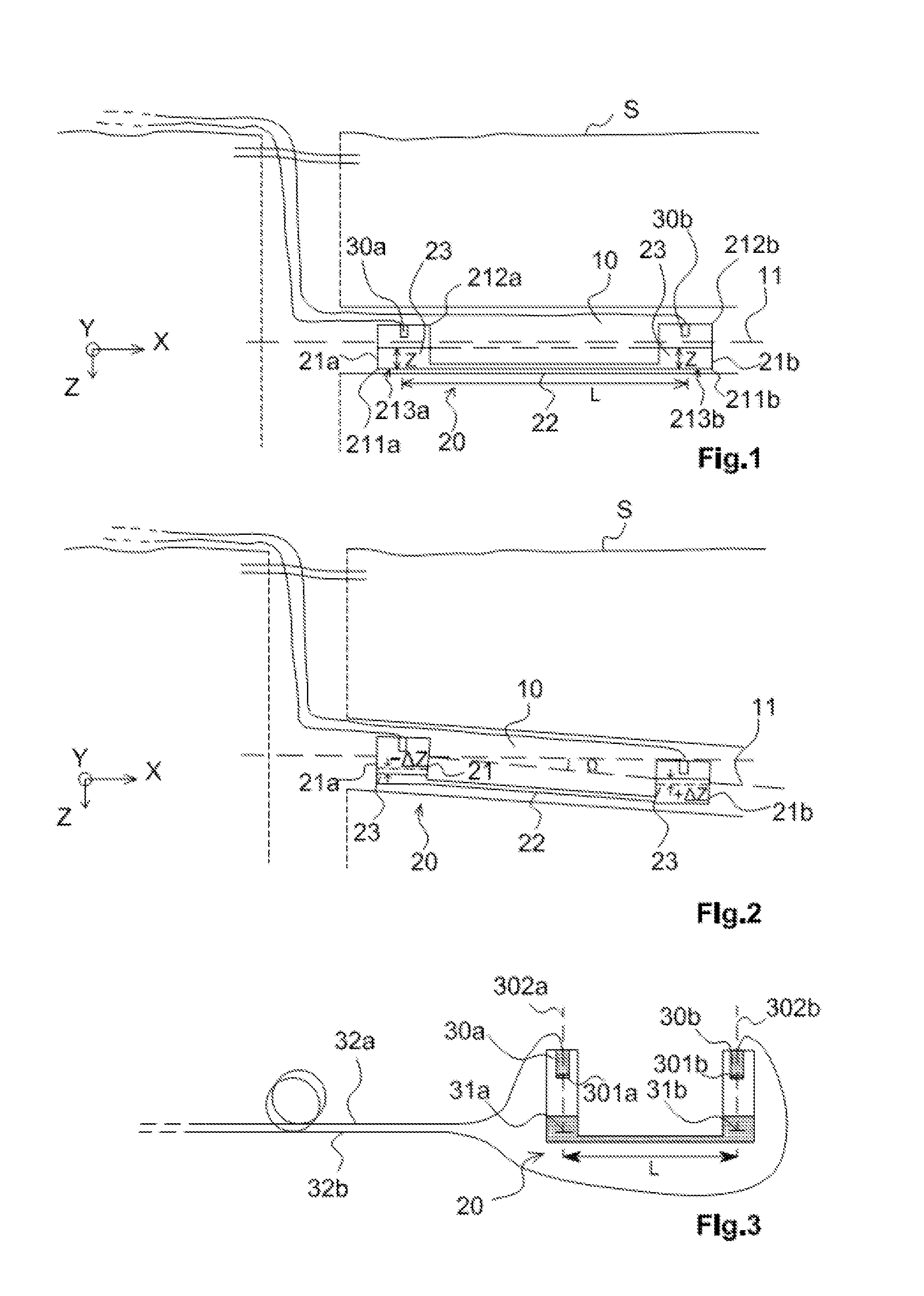
[0060]One example of a measuring system in accordance with the invention for measuring the tilt variation of a structure includes a tiltmeter 20 shown diagrammatically in FIG. 1.

[0061]In the example shown, this structure is the earth's crust into which a deep bore 10 has been drilled and into which the tiltmeter 20 is introduced. The embodiment of the tiltmeter is described in detail in its application to measuring the tilt variation of the bore for seismological applications. This choice is not limiting on the invention and the invention applies equally to other applications, such as in the field of civil engineering, for example. The coupling mode is also not limiting on the invention, and these instruments can equally be installed along the walls of a tunnel or a horizontal gallery.

[0062]Throughout the description, unless otherwise indicated, at the level of the bore drilled from a ground surface S, the terms horizontal and vertical will be defined relative to terrestrial gravity...


PUM


Abstract

A tiltmeter to measure a variation in inclination of a structure from a given starting position. The tiltmeter has two pots, each pot contains an identical volume and identical height of an identical liquid. A communication device connects the two pots and allows the liquid to flow between the two pots by the principle of communicating vessels. Two optical measuring devices are provided, one optical measuring device per pot. Each optical measuring device measures a variation in height of the level of liquid in the associated pot. The optical measuring devices are fiber optic devices coupled to a common light source.

Description

FIELD OF THE INVENTION[0001]The present invention concerns a tiltmeter, that is to say a device intended to measure tilt variations of structures. The invention is notably usable in horizontal bores or galleries, in the field of civil engineering, for the surveillance of structures and buildings, and generally wherever precise monitoring of the stability of a structure is required, in particular in the long term.PRIOR ART[0002]Tilt variations of structures are measured frequently and notably in the case of measurement of geophysical deformations, more specifically seismic or volcanic deformations. Such measurements are also carried out to warn of the possible danger of collapse of buildings or a portion thereof or to monitor changes in the storage of fluids in geological storage sites and the migration of these fluids into the permeable layer. These measurements can also be used to monitor the horizontally of large industrial structures.[0003]During an earthquake, in fault areas, th...

Claims


Application Information

Patent Timeline
IPC IPC(8): G01C9/06G01B11/26
CPCG01C9/06G01C2009/066G01B11/26G01C5/04G01C9/22
Inventor BOUDIN, FREDERICK
Owner CENT NAT DE LA RECHERCHE SCI
Why Eureka
Try Eureka