Light source device and projector using the same

a technology of light source device and projector, which is applied in the direction of instruments, lighting and heating apparatus, brightness and chrominance signal processing circuits, etc. it can solve the problems of complex control and complex manufacturing process of phosphor, and achieve simplified configuration of optical systems, simplified manufacturing process of phosphor, and improved layout freedom

Active Publication Date: 2015-11-05
RICOH KK
View PDF1 Cites 16 Cited by
  • Summary
  • Abstract
  • Description
  • Claims
  • Application Information

AI Technical Summary

Benefits of technology

[0008]It is, therefore, an object of the present invention to provide a light source device in which a manufacturing process of a phosphor can be simplified, a configuration of an optical system can be simplified, and layout freedom can be improved, and a projector using the light source device. The light source device includes a single light source section and is capable of generating a color image without separating a fluorescence area of the phosphor into an area which emits green fluorescence and an area which emits red fluorescence.

Problems solved by technology

Therefore, the manufacturing process of the phosphor is complicated.
As such, control of the phosphor is complicated.

Method used


Image

  • Light source device and projector using the same
  • Light source device and projector using the same
  • Light source device and projector using the same

Examples


embodiment 1

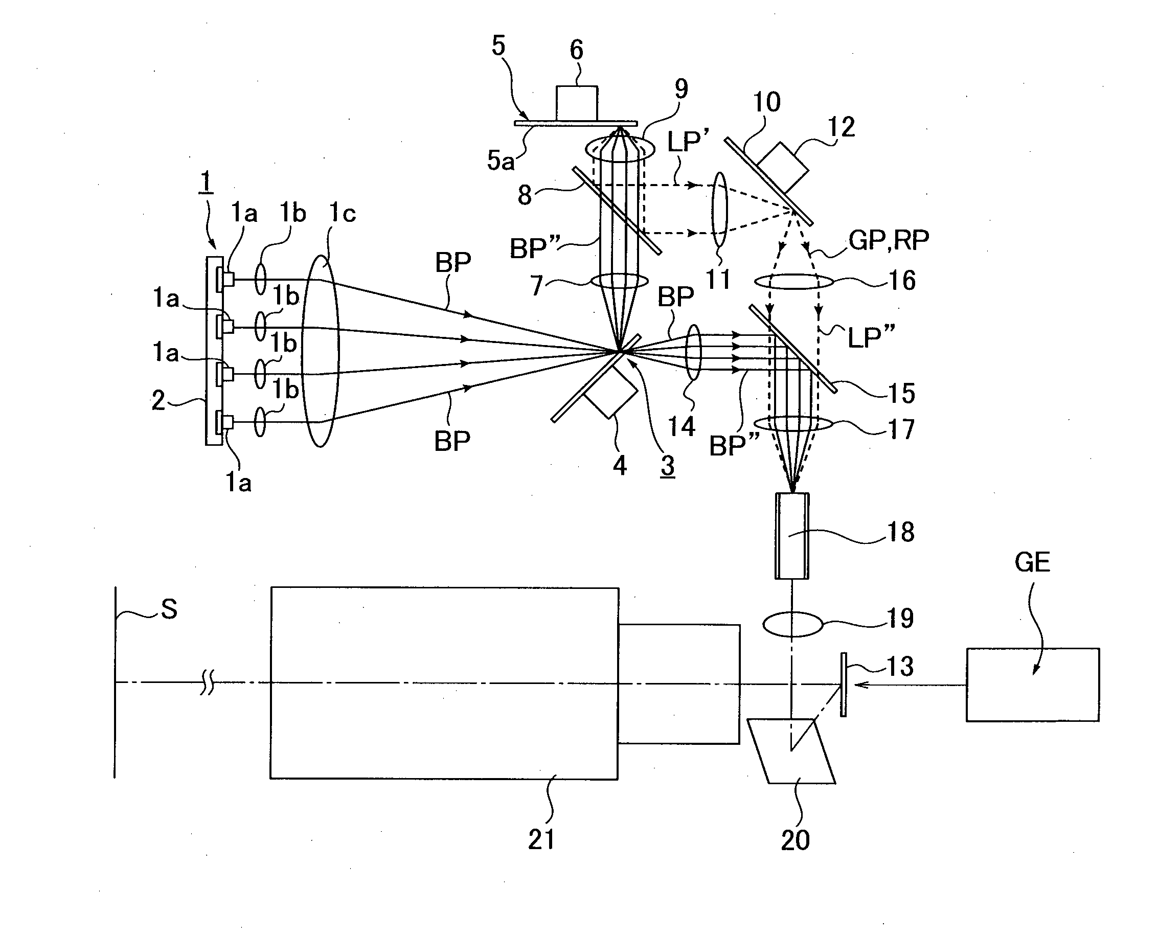
[0037]FIG. 1 is an optical view illustrating a main configuration of an optical system of a projector which includes a light source device according to Embodiment 1 of the present invention. In FIG. 1, numeral 1 represents a light source section. The light source section 1 is schematically configured of a laser diode (LD) as a laser light source, a coupling lens 1b, and a light-condensing lens 1c.

[0038]A plurality of laser diodes 1a is disposed on a driving circuit board 2, and the coupling lens 1b is disposed corresponding to each laser diode 1a. A laser beam emitted from the laser diode 1a is concentrated by the coupling lens 1b to be a parallel light flux and guided to the light-condensing lens 1c.

[0039]The light-condensing lens 1c concentrates the laser beam after becoming a parallel light flux through each coupling lens 1c. The laser diode 1a emits a blue (B) laser beam BP as one of blue (B) light, red (R) light, and green (G) light. However, a laser diode which emits a green...

modified example of embodiment 1

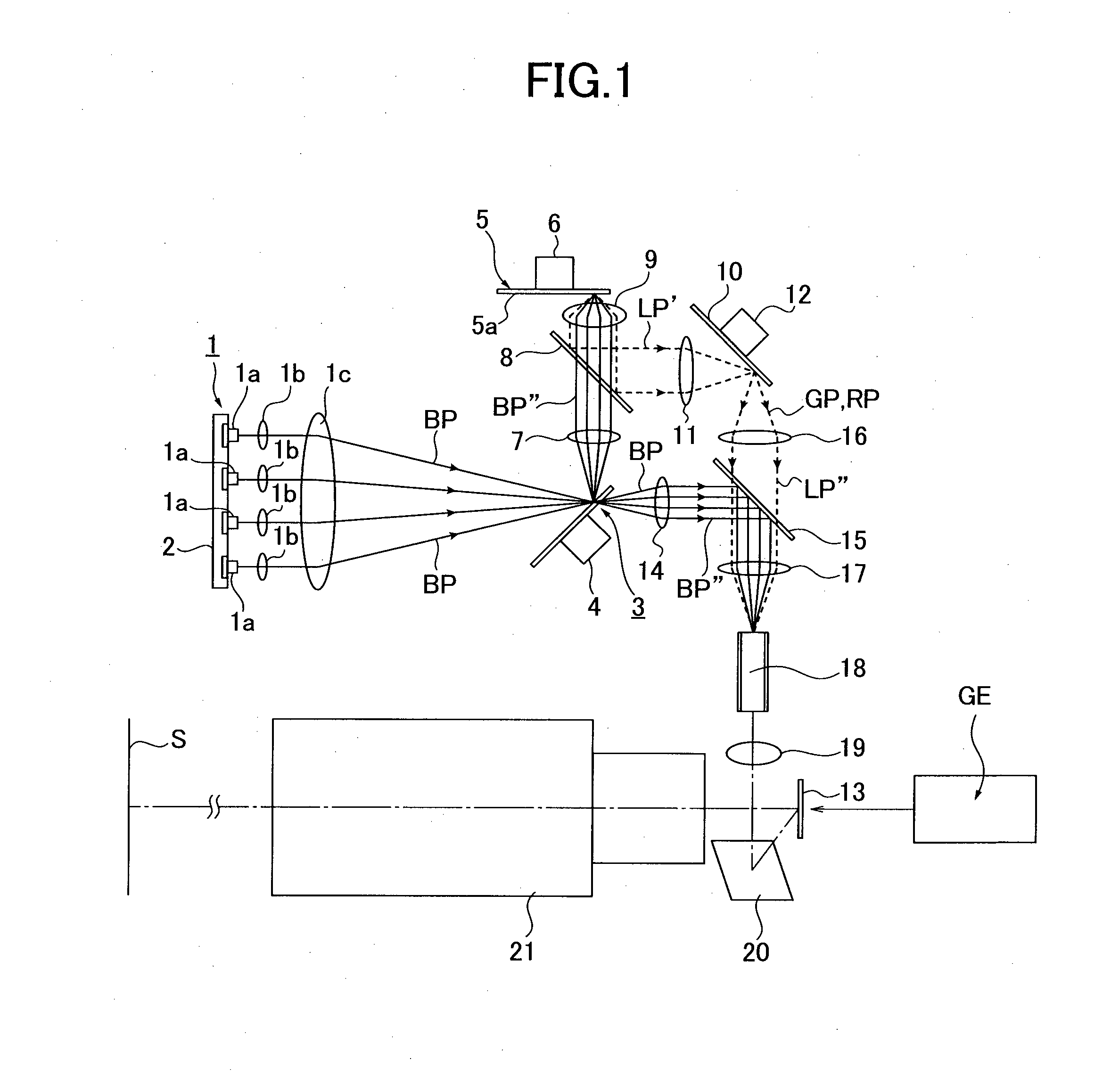
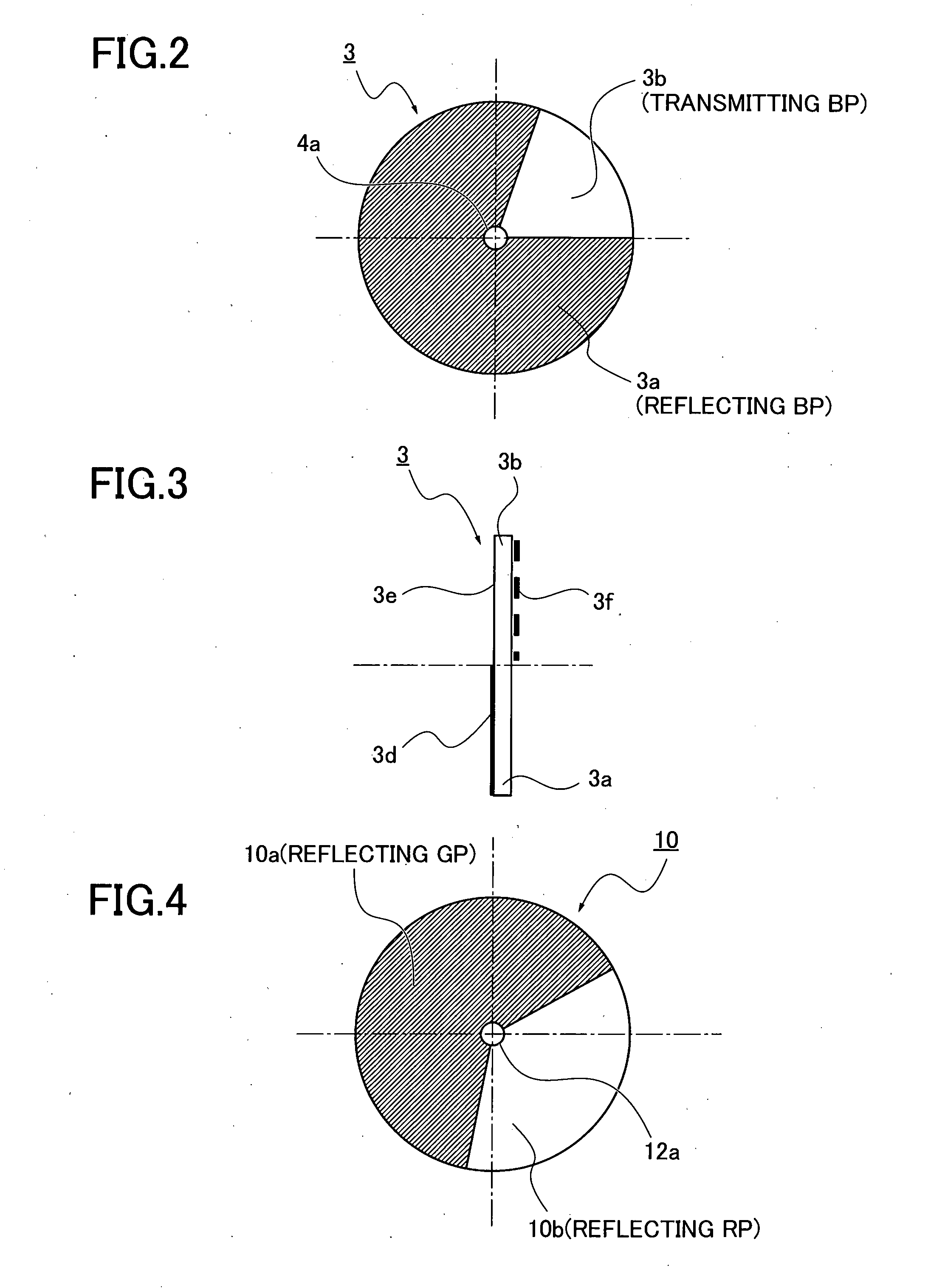
[0070]FIG. 8 illustrates a modified example of the optical system according to Embodiment 1. The phosphor 5 is disposed in the transmitting light path in which the blue laser light BP which has transmitted through the transmitting area 3b of the light path-switching disk 3 travels. Also, a dichroic mirror 15 is disposed in the reflecting light path in which the blue laser beam BP which is reflected by the reflecting area 3a of the light path-switching disk 3 travels. In other words, a light path in which the light emitted from the light source section 1 travels towards the image-forming element through the light-condensing lens 14 and the dichroic mirror 15 is disposed. And also, a light path in which the fluorescence excited by the color light emitted from the light source section 1 travels towards the color-changing disk 10 through the light-condensing lens 9, dichroic mirror 8 and light-condensing lens 11 is disposed.

[0071]In the modified example, as shown in FIG. 9, the angle of...

embodiment 2

[0076]FIG. 12 is an optical view illustrating an optical system of a projector according to Embodiment 2 of the present invention. Herein, a dichroic mirror which transmits the blue laser beam BP and guides it to the light path-switching disk 3, and reflects the light of another color than blue and guides it to the color-changing disk 10 is disposed between the light path-switching disk 3 and the condensing lens 1c.

[0077]A concave lens 1c′ which converts the laser beam BP into the parallel light flux is disposed between the light-condensing lens 1c and the dichroic mirror 8. The light path-switching disk 3 includes a reflecting area 3a on which the fluorescent coat 5a is applied and a transmitting area 3b on which a fluorescent coat is not applied as illustrated in FIGS. 13, 14.

[0078]Similar to Embodiment 1, a reflection-preventing coat 3e is formed in the transmitting area 3b on the surface in which the laser beam BP irradiates. A light-condensing lens 9 is disposed between the di...


PUM


Abstract

A light source device including: a light source section which generates any one of blue light, red light, and green light; a phosphor which generates a fluorescence including the two colors other than the color of the light emitted from the light source section; a color-changing section which changes one of the two colors of the fluorescence emitted from the phosphor to another color regularly and irradiates it to the image-forming element; and a light path-switching section which switches a light path in which a fluorescence excited by the color light emitted from the light source section passes towards the color-changing section and a light path in which the color light emitted from the light source section passes towards the image-forming element regularly.

Description

PRIORITY CLAIM[0001]The present application is based on and claims priority from Japanese Patent Application Numbers 2012-282475, filed on Dec. 26, 2012, and 2013-182894, filed Sep. 4, 2013, the disclosures of which are hereby incorporated by reference herein in their entireties.TECHNICAL FIELD[0002]The present invention relates to an improvement of a light source device which temporarily irradiates each of blue light, red light, and green light to an image-forming element to form a color image on a screen by the image-forming element, and a projector using the light source device.BACKGROUND ART[0003]A projector which temporarily irradiates blue light, red light, and green light to an image-forming element in order to form a color image on a screen by the image-forming element is conventionally known (for example, registered Japanese patent No. 4711154).[0004]The projector disclosed in the above JP patent No. 4711154 includes a blue laser diode, a phosphor, and a dichroic mirror as ...

Claims


Application Information

Patent Timeline
Patent Type & Authority Applications(United States)
IPC IPC(8): G03B21/20F21K99/00
CPCG03B21/204G03B21/2013F21K9/56G03B21/2066G02B26/008G03B21/142G03B21/20H04N9/315H04N9/3161G03B33/08H04N9/3114H04N9/3158H04N9/3182G02B27/102F21K9/64F21V9/30H04N9/77
Inventor MAEDA, IKUOFUJITA, KAZUHIROMURAI, TOSHIHARUTAKAHASHI, TATSUYANISHIMORI, TAKEHIRO
Owner RICOH KK
Why Eureka
Try Eureka