Container sealing device

Active Publication Date: 2015-11-12
TOKAN KOGYO CO LTD
21 Cites 14 Cited by

AI-Extracted Technical Summary

Problems solved by technology

Note that the separation part is considered to be fixed to the support part in advance by causing the second screwing part to have a mere fitting structure of irregularity, but...

Benefits of technology

[0017]In still another viewpoint of the present invention, a score is provided between the body part of the inner plug and the separation par...

Abstract

An object is to provide a container sealing device which can perform an opening of an inner plug with a clear opening feeling. An inner plug 10 is assembled in advance to an upper closure 20 by using a second screwing part 52. At this time, since an assembling interval between a separation part 12 and the upper closure 20 can be adjusted by tip end parts 16t and 20u of a cylindrical part 16 which are first stoppers and the small-diameter cylinder part 20d, the second screwing part 52 can be brought into a lock state of being screwed to the deepest position or a state close to that. In opening the plug, the first screwing part 51 is loosened the second screwing part 52 is tightened, and the separation part 12 can be rapidly and reliably separated from a body part 10b of the inner plug 10.

Application Domain

Technology Topic

Image

  • Container sealing device
  • Container sealing device
  • Container sealing device

Examples

  • Experimental program(1)

Example

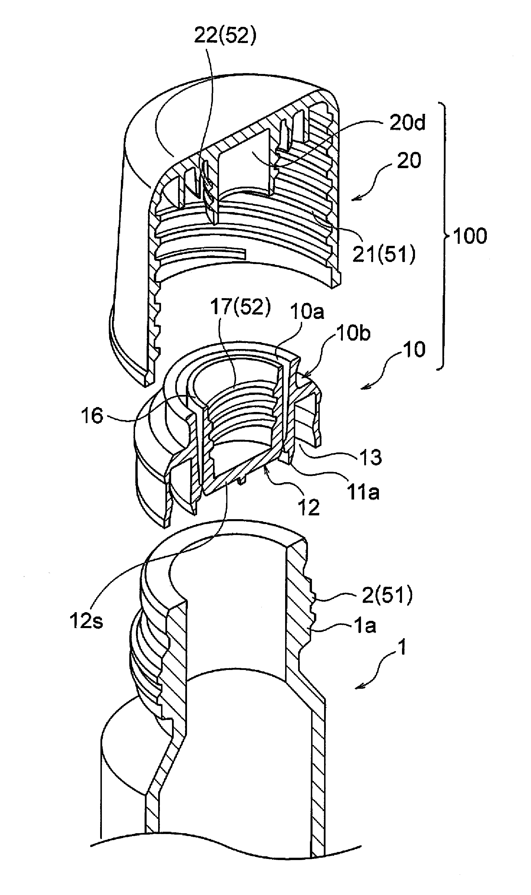
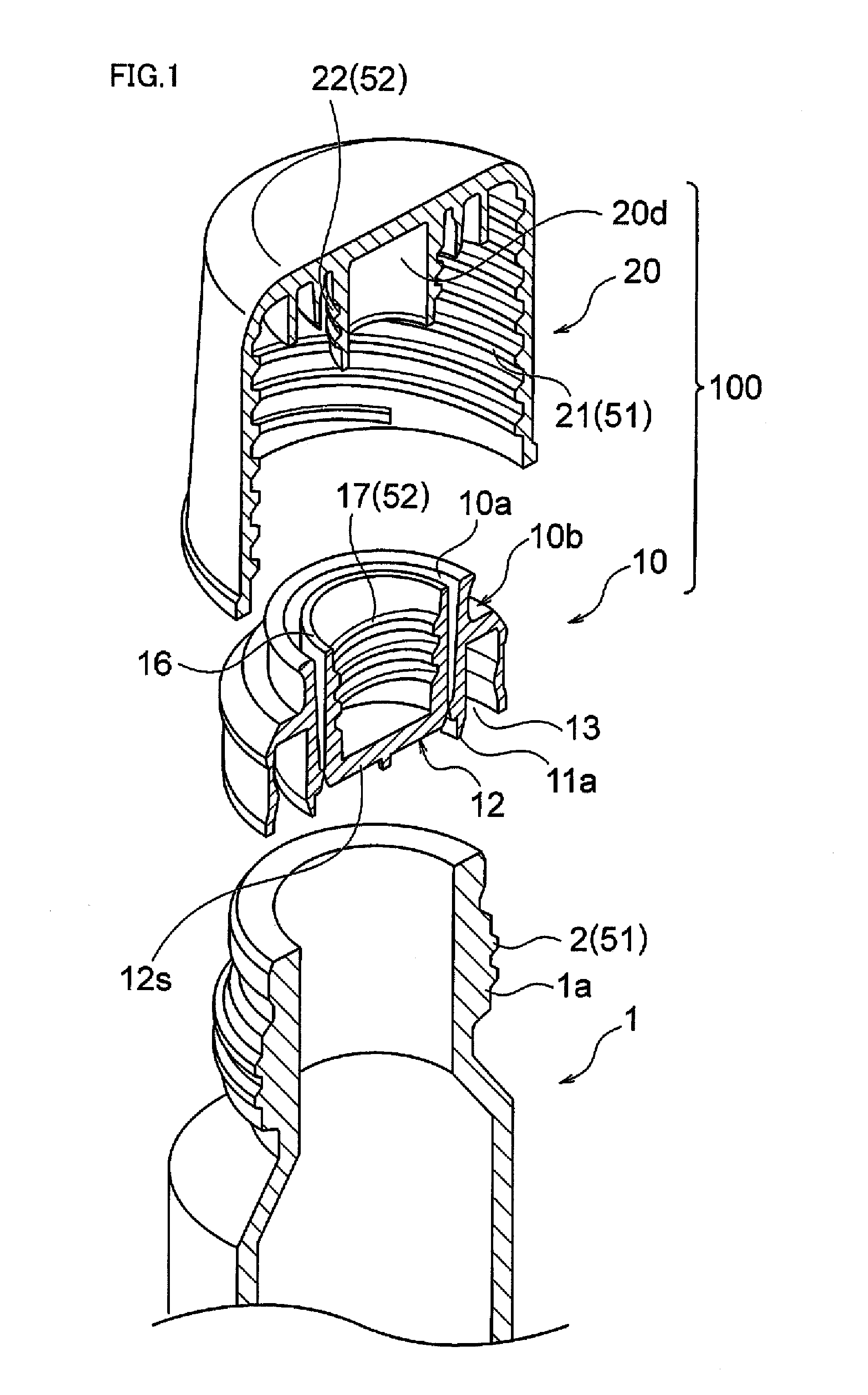
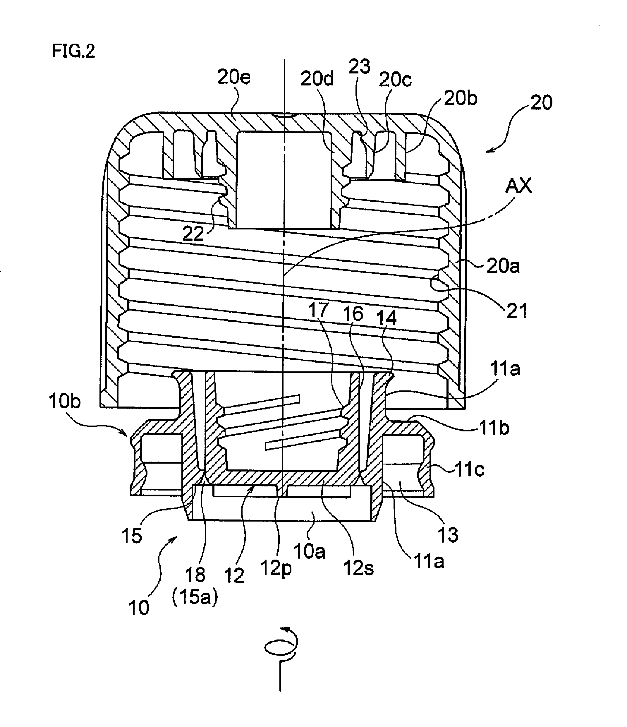
[0024]FIGS. 1 to 5 illustrate an embodiment of a container sealing device according to the present invention.
[0025]An illustrated sealing device 100 is constituted of an inner plug 10 locked by a mouth part 1a of a container 1 through fitting or the like, and an upper closure 20 screwed with the mouth part 1a of the container 1 so as to cover an extraction port 10a of the inner plug 10.
[0026]The inner plug 10 is an integrally molded produce made of a resin and is provided with a body part 10b locked by or fixed to the container 1 and a separation part 12.
[0027]As illustrated in FIG. 2 and the like, the body part 10b of the inner plug 10 forms the extraction port 10a of a content of the container 1 and has a cylindrical base part 11a which is a cylindrical member extending along an axial center AX, a flange part 11b extending outward in a radial direction from an outer peripheral surface of an intermediate part of the cylindrical base part 11a, and an annular wall part 11c which is an annular member extending downward from an outer end of the flange part 11b. These cylindrical base part 11a, the flange part 11b, and the annular wall part 11c define an annular recess part 13 fitted with the mouth part 1a of the container 1. In addition, a lip part 14 extending outward is formed at an upper end of the cylindrical base part 11a.
[0028]The separation part 12 of the inner plug 10 is provided with a disc-shaped sealing body 12s arranged on a bottom part and a cylindrically-shaped cylindrical part 16 extending upward from an outer edge of this sealing body 12s. An outer-periphery side boundary part between the outer edge of this sealing body 12s and a lower end part of the cylindrical part 16 is connected to the body part 10b of the inner plug 10 by an annular connection part 15. An annular notch 18 is formed on a lower surface of the connection part 15. This notch 18 serves as a part of a score 15a cut off when opening the plug. A cross-shaped protrusion part 12p is provided on the lower surface side of the sealing body 12s, in order to facilitate screwing of the inner plug 10 into the upper closure 20 by rotating the inner plug 10 including the separation part 12 when the inner plug 10 is assembled to the upper closure 20. The cylindrical part 16 is arranged concentrically and separately inside the cylindrical base part 11a on an outer side. There is formed a female thread 17 to be screwed with a male thread 22 provided on a small-diameter cylinder part 20d of the upper closure 20 which will be described later, on an inner peripheral surface of the cylindrical part 16.
[0029]The upper closure 20 is an integrally molded product made of a resin and is provided with a cylindrical peripheral wall part 20a which forms an appearance; and a large-diameter cylinder part (second inner cylinder part) 20b, a middle-diameter cylinder part 20c, and the small-diameter cylinder part (first inner cylinder part) 20d concentrically with the peripheral wall part 20a therein, and they are continuously provided by a ceiling wall 20e. A female thread 21 screwed with a male thread 2 formed on the outer peripheral side surface of the mouth part 1a of the container 1 is formed on an inner peripheral surface of the peripheral wall part 20a, and the male thread 22 screwed with the female thread 17 formed on the inner peripheral side surface of the cylindrical part 16 of the separation part 12 provided on the inner plug 10 is formed on an outer peripheral surface of the small-diameter cylinder part (first inner cylinder part) 20d.
[0030]In the above, the male thread 21 of the peripheral wall part 20a of the upper closure 20 and the male thread 2 of the mouth part 1a of the container 1 constitute a first screwing part 51 which enables attachment and detachment of the upper closure 20 with respect to the container 1. Furthermore, the female thread 17 of the cylindrical part 16 of the inner plug 10 and the male thread 22 of the small-diameter cylinder part (first inner cylinder part) 20d of the upper closure 20 constitute a second screwing part 52 for tightening and fixing the separation part 12 of the inner plug 10 to the small-diameter cylinder part 20d of the upper closure 20. That is, the small-diameter cylinder part 20d of the upper closure 20 functions as a support part for catching the separation part 12 by the second screwing part 52 and separating the separation part 12 from the inner plug 10. The first screwing part 51 and the second screwing part 52 are in a mutually reverse thread relation. Namely, when the first screwing part 51 is screwed back so as to be loosened by rotating the peripheral wall part 20a of the upper closure 20 in a counterclockwise direction when seen from an upper side, the small-diameter cylinder part (support part) 20d of the upper closure 20 is rotated in a counterclockwise direction when seen from the upper side, and the second screwing part 52 is tightened. Here, for example, the screwing direction or the like of the second screwing part 52 will be described in detail. For the cylindrical part 16 of the inner plug 10, the upper side along the axial center AX is the screwing direction for screwing with the small-diameter cylinder part 20d of the upper closure 20 by rotation in the counterclockwise direction when seen from a lower side, whereas a lower side along the axial center AX is the anti-screwing direction for screwing back the small-diameter cylinder part 20d by rotation in the clockwise direction. For the small-diameter cylinder part 20d, the lower side along the axial center AX is the screwing direction for screwing with the cylindrical part 16 by rotation in the counterclockwise direction when seen from the upper side, whereas the upper side along the axial center AX is the anti-screwing direction for screwing back the cylindrical part 16 by rotation in the clockwise direction when seen from the upper side.
[0031]As illustrated in FIGS. 3A and 3B, a tip end part 16t of the cylindrical part 16 of the inner plug 10 is brought into contact with a lower surface 20t of the ceiling wall 20e of the upper closure 20 exposed between the base part of the middle-diameter cylinder part 20c and the base part of the small-diameter cylinder part 20d of the upper closure 20. Similarly, a tip end part 20u of the small-diameter cylinder part 20d of the upper closure 20 is brought into contact with an inner-surface corner part 12u of the separation part 12 of the inner plug 10. The tip end part 16t of the cylindrical part 16 and the tip end part 20u of the small-diameter cylinder part 20d function as first stoppers for regulating their mutual assembling interval between the separation part 12 of the inner plug 10 and the upper closure 20. Furthermore, a tip end part 20v of the large-diameter cylinder part 20b of the upper closure 20 is in contact with an upper surface 11v of the flange part 11b of the inner plug 10. The tip end part 20v of the large-diameter cylinder part 20b functions as a second stopper regulating their mutual assembling interval between the upper closure 20 and the body part 10b of the inner plug 10. Note that an outer peripheral surface 20g of the middle-diameter cylinder part 20c provided at the upper closure 20 and an inner side surface 11g of a tip end part 11w provided at the cylindrical base part 11a of the inner plug 10 are in close contact with each other. As a result, when sealing after opening the plug, the inside of the container 1 can be kept liquid-tight.
[0032]The inner plug 10 and the upper closure 20 constituted as described above are screwed with each other by engaging the female thread 17 which is a reverse thread of the inner plug 10 with the male thread 22 which is a reverse thread of the upper closure 20, and by rotating the inner plug 10 in a counterclockwise direction when seen from the inner plug 10 side or by rotating the upper closure 20 in the counterclockwise direction when seen from the upper closure 20 side. When the inner plug 10 is supported in screwing, a tool can be utilized, and the protrusion part 12p of the separation part 12 is supported by a chuck part of the tool. The upper closure 20 and the inner plug 10 are tightened to the deepest position and integrated. Namely, the small-diameter cylinder part (first inner cylinder part) 20d of the upper closure 20 is fitted so as to be pushed into the inner plug 10 until the tip end part 16t of the cylindrical part 16 reaches a state of being brought into contact with the lower surface 20t of the ceiling wall 20e of the upper closure 20 or is screwed into the inner plug 10 until the tip end part 20u of the small-diameter cylinder part 20d reaches a state of being brought into contact with the inner-surface corner part 12u of the separation part 12 of the inner plug 10. At this time, the tip end part 20v of the large-diameter cylinder part (second inner cylinder part) 20b of the upper closure 20 is brought into contact with the upper surface 11v of the flange part 11b of the inner plug 10.
[0033]In the state where the inner plug 10 and the upper closure 20 are engaged with each other as above, the interval between the inner plug 10 and the upper closure 20 is adjusted, and as illustrated in FIG. 3B and the like, the tip end part 16t of the cylindrical part 16 is accommodated in a recess part 23 formed at a base part between the middle-diameter cylinder part 20c and the small-diameter cylinder part 20d. In addition, the lip part 14 formed at the tip end of the cylindrical base part 11a is positioned in a state of being brought into contact with the lower surface 20t of the ceiling wall 20e of the upper closure 20.
[0034]Then, the cap (an assembly of the inner plug 10 and the upper closure 20) assembled as described above is locked by the container 1 by fitting the annular recess part 13 defined by the cylindrical base part 11a of the inner plug 10, the flange part 11b and the annular wall part 11c, with the mouth part 1a of the container 1, as illustrated in FIG. 4. Namely, the upper closure 20 is screwed with the mouth part 1a of the container 1, and the body part 10b of the inner plug 10 reaches a state of being fitted air-tightly with the mouth part 1a. Specifically, the female thread 21 with a forward thread formed on the peripheral wall part 20a of the upper closure 20 is engaged with the male thread 2 with a forward thread formed on the mouth part 1a of the container 1, and, for example, the upper closure 20 is rotated in a clockwise direction when seen from the upper closure 20 side or the container 1 is rotated in the clockwise direction when seen from the container 1 side, whereby the both are screwed with each other. Here, when the annular wall part 11c and the like ride over a tip end 1b of the mouth part 1a of the container 1, the inner plug 10 is subjected to an action of screwing back by receiving a torque of a left thread. However, the inner plug 10 is pressed into the upper closure 20 by the mouth part 1a of the container 1, and the inner plug 10 is substantially fixed to the upper closure 20 and is hardly screwed back due to an influence of friction between the upper closure 20 and the inner plug 10 and the like. Furthermore, displacement of the body part 10b of the inner plug 10 is prevented by the tip end part 20v of the large-diameter cylinder part 20b which is the second stopper, and a relatively large load or stress is prevented from being applied to the separation part 12 via the body part 10b.
[0035]Not that, when the cap (the assembly of the inner plug 10 and the upper closure 20) is mounted on the mouth part 1a of the container 1, the assembly of the inner plug 10 and the upper closure 20 can also be capped (forcedly pushed in and fixed) instead of being screwed into the mouth part 1a. In this case, since there exists the tip end part 20v of the large-diameter cylinder part 20b which is the second stopper, large displacement of the body part 10b of the inner plug 10 with respect to the upper closure 20 can be avoided in capping, and damage can be prevented from being caused in the periphery of the separation part 12, by application of a relatively large load or stress to the separation part 12 via the body part.
[0036]Hereinafter, an opening operation or unsealing operation of the cap structure of the aforementioned embodiment will be described by referring to FIGS. 4 and 5.
[0037]First, as illustrated in FIG. 4, the upper closure 20 is at an initial position (a state of being screwed into the deepest position or close to that) before a rotating operation of the screwing part, while the separation part 12 and the cylindrical part 16 are in a connected state, that is, in a state where the score 15a of the connection part 15 is not cut off, and thus an opening part 3 of the container 1 is in a sealed state.
[0038]From this state, the upper closure 20 is moved upward by rotating the upper closure 20 in a loosening direction, that is, in a counterclockwise direction. Along with that, since the separation part 12 is screwed with the upper closure 20 through reverse threads, the separation part 12 is subjected to an action of moving upward with respect to the upper closure 20. At that time, since the separation part 12 is screwed with the upper closure 20 through reverse threads substantially to the deepest position, further tightening is not performed or tightening somewhat progresses and enters a lock state where movement to the direction of the upper closure 20 is prevented. Namely, the separation part 12 is moved upward together with the upper closure 20 while rotating in the counterclockwise direction when seen from above with respect to the body part 10b. During that period, since a stress concentrates on the notch 18 or the score 15a of the inner plug 10, the connection part 15 is sheared, the separation part 12 is removed from the cylindrical base part 11a and the plug is opened. In such opening of the plug, since the separation part 12 is elevated together with the upper closure 20 while rotating, a clear opening feeling can be generated when the separation part 12 is separated from the cylindrical base part 11a by breakage of the score 15a. Namely, a snap sound is generated in the opening of the plug, and a torque required for rotation of the upper closure 20 is rapidly reduced.
[0039]In this state, in the separation part 12, as illustrated in FIG. 3B, for example, the tip end part 16t of the cylindrical part 16 is brought into contact with the lower surface 20t in the recess part 23, with the result that a lock state by screwing is maintained, and is held by the upper closure 20.
[0040]Furthermore, the upper closure 20 separates from the cylindrical base part 11a by rotating the upper closure 20 in the loosening direction, as illustrated in FIG. 5, whereby the contents in the container 1 can be poured. At this time, the separation part 12 is ensured by the upper closure 20 and is in a lock state with respect to the upper closure 20, and thus there is no risk of removal. Namely, once being opened, the separation part 12 fixed to the inner plug 10 side is fixed to the upper closure 20 side.
[0041]A state after the opening of the plug will be described by referring to FIGS. 5, 4, and 3B. When the female thread 21 of the upper closure 20 is screwed with the male thread 2 of the mouth part 1a of the container 1 and the upper closure 20 is rotated in the clockwise direction, the lip part 14 formed at an upper end of the cylindrical base part 11a of the inner plug 10 is brought into contact with the lower surface 20t of the ceiling wall 20e of the upper closure 20, and also, the outer peripheral surface 20g of the middle-diameter cylinder part 20c is brought into close contact with the inner side surface 11g of the cylindrical base part 11a on the tip end side. As a result, sealing of the opening part 3 is achieved. Note that, in FIG. 4 and the like, the score 15a is not cut off, but accurately, once the opening of the plug is performed, the score 15a is put into a state of having been cut off.
[0042]According to the container sealing device described above, the inner plug 10 is assembled to the upper closure 20 by using the second screwing part 52 in advance. At this time, since the assembling interval between the separation part 12 and the upper closure 20 can be adjusted by the tip end parts 16t and 20u of the cylindrical part 16 which is the first stopper and the small-diameter cylinder part 20d, the second screwing part 52 can be brought into a lock state of being screwed to the deepest position or a state close to that. After that, the attachment of the sealing device 100 to the container 1, that is, sealing becomes possible by screwing the upper closure 20 with the inner plug 10 into the container 1. In opening the plug, the upper closure 20 is rotated in the loosening direction with respect to the container 1. Namely, the first screwing part 51 is loosened by rotating the upper closure 20 so as to be screwed back, but along with that, the second screwing part 52 which has been already substantially locked is tightened, and the separation part 12 can be rapidly and reliably separated from the body part 10b of the inner plug 10. As a result, after separation, that is, after opening the plug, the separation part 12 becomes less likely to be removed from the upper closure 20, and is reliably held. As described above, a clear opening feeling such as generation of a snap sound or sudden reduction in resistance against rotation can be presented by separating the separation part 12 from the body part 10b of the inner plug 10 while tightening the second screwing part 52 which has been substantially locked.
[0043]Hereinbefore, the container sealing device according to the present embodiment has been described, but the container sealing device according to the present invention is not limited to the above. For example, in the present embodiment, specifications such as a pitch, a winding number, a thread height and the like of the male thread 2 and the female thread 21 constituting the first screwing part 51 can be appropriately modified in accordance with application. Furthermore, the specifications such as a pitch, a winding number, a thread height and the like of the male thread 22 and the female thread constituting the second screwing part 52 can also be appropriately modified in accordance with application.
[0044]The cylindrical part 16 of the inner plug 10 and the small-diameter cylinder part 20d of the upper closure 20 can be switched inside and outside. Also in this case, the male thread of the cylindrical part 16 and the female thread of the small-diameter cylinder part 20d constitute the second screwing part 52 in the reverse thread relation with respect to the first screwing part 51.
[0045]As illustrated in FIG. 6, as a state before opening of the plug, the tip end part 20u of the small-diameter cylinder part 20d of the upper closure 20 can be spaced away from the inner-surface corner part 12u of the separation part 12. Alternatively, although not shown, the tip end part 16t of the cylindrical part 16 of the inner plug 10 can be spaced away from the lower surface 20t of the ceiling wall 20e of the upper closure 20. However, when either one of the tip end parts 20u and 16t is spaced away, the tip end part 20u on an inner side is preferably spaced away from the inner-surface corner part 12u from the viewpoint of preventing removal or the like of the separation part 12 by protecting the second screwing part 52 from the contents in the container 1.
[0046]In the above, it is assumed that, in a state where the inner plug 10 is set on the upper closure 20 before sealing, the both are tightened to the deepest position, but at that time, the tip end part 20v of the large-diameter cylinder part 20b functioning as the second stopper can also be somewhat spaced away from the upper surface 11v of the flange part 11b of the inner plug 10. However, if the interval between the tip end part 20v and the upper surface 11v is too large, stress is easily applied between the cylindrical base part 11a and the cylindrical part 16 when the upper closure 20 is to be screwed into the container 1 together with the inner plug 10 and is fitted, and thus it is necessary to pay attention.
[0047]The female thread 17 and the male thread 22 constituting the second screwing part 52 are not limited to those formed continuously and spirally, but can be composed of a plurality of separate parts.
[0048]In the above, assumption is made that the container 1 has a bottle shape of a PET bottle or the like. However, the container 1 is not limited to the bottle as described above, but can have a bag shape made of a film or can be any other polygonal paper packages. At this time, the inner plug 10 can have a spout shape with a flange and can be fixed to the container by fusion or the like.
[0049]The first screwing part 51 may be provided not only between the upper closure 20 and the container 1, but also between the upper closure 20 and the inner plug 10 fixed to the container 1. When the first screwing part 51 is provided between the upper closure 20 and the inner plug 10, at least either one of the first screwing part 51 and the second screwing part 52 is forcedly pushed in and fitted, in assembling. Therefore, it is possible to facilitate mounting of the inner plug 10 to the upper closure 20 by, for example, forming the thread of the first screwing part 51 or the second screwing part 52 into a shape that can be easily pushed in.

PUM

no PUM

Description & Claims & Application Information

We can also present the details of the Description, Claims and Application information to help users get a comprehensive understanding of the technical details of the patent, such as background art, summary of invention, brief description of drawings, description of embodiments, and other original content. On the other hand, users can also determine the specific scope of protection of the technology through the list of claims; as well as understand the changes in the life cycle of the technology with the presentation of the patent timeline. Login to view more.

Similar technology patents

Mercury recovery apparatus

InactiveUS6866814B2Reduce thermal degradationFacilitate separationUsing liquid separation agentSolid waste disposalEnvironmental chemistryFluorescent lamp
Owner:PANASONIC CORP

Classification and recommendation of technical efficacy words

  • Reliable seal
  • Facilitate separation

Seal for controlled evacuation ostomy appliance

ActiveUS20070191794A1Reliable sealSurgeryMedical devicesOstomy appliancesMembrane configuration
Owner:CONVATEC TECH INC

Sealing arrangements

Owner:ANSALDO ENERGIA SWITZERLAND AG

Pneumatic suture instrument

InactiveUS7232446B1Facilitate separationSuture equipmentsSewing apparatusSurgical sutureSurgical Staplers
Owner:FARRIS ALEX F

Imprint lithography with improved substrate/mold separation

ActiveUS20080122144A1Easily separateFacilitate separationPlaten pressesMouldsLateral displacementEngineering
Owner:ZHANG WEI +3

Lazy susan device with snap fit top and base

InactiveUS8544390B1Easily take apartFacilitate separationTable equipmentsStands/trestlesEngineeringRest position
Owner:BAHNSEN SCOTT M

Modular mobile telephone apparatus

InactiveUS20050107046A1Prevent be damageFacilitate separationWing fastenersDevices with bluetooth interfacesLogic circuitryFunctional module
Owner:BRITISH TELECOMM PLC

Card supplying mechanism and card supplying method

ActiveUS20060065718A1Facilitate separationReduce load actConveying record carriersData sortingElectric machineryMaximum diameter
Owner:NISCA KK
Why Eureka
Try Eureka