Unlock instant, AI-driven research and patent intelligence for your innovation.

Method of predicting crack growth and information processing device therefor

Active Publication Date: 2015-11-12
THE CHUGOKU ELECTRIC POWER CO INC
View PDF3 Cites 7 Cited by
  • Summary
  • Abstract
  • Description
  • Claims
  • Application Information

AI Technical Summary

Benefits of technology

The present invention provides methods and devices for predicting the growth of cracks in members with accurate and easy predictions. This helps to better prevent damage and minimize risks associated with these cracks.

Problems solved by technology

This is a labor-intensive process because meshes (FEM models) need to be re-meshed for each predicted depth of a growing crack and is also uneconomical because it is necessary to use a sophisticated information processing device.

Method used


Image

  • Method of predicting crack growth and information processing device therefor
  • Method of predicting crack growth and information processing device therefor
  • Method of predicting crack growth and information processing device therefor

Examples


Embodiment Construction

[0050]Embodiments are described below with reference to the drawings.

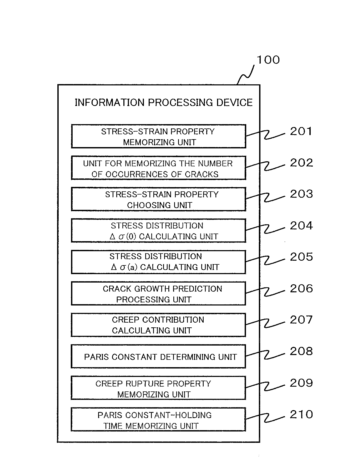
[0051]FIG. 1 shows major hardware components of an information processing device 100 to be used for achieving a crack growth analysis system according to one or more embodiments. The crack growth analysis system of one or more embodiments is used in analysis or diagnosis of thermal cracks or fatigue cracks which appear in members of, for example, structures or various instruments used under high temperature conditions, such as a steam turbine or a boiler in a power plant (e.g., a thermal power plant or a nuclear power plant).

[0052]As shown in the figure, the information processing device 100 comprises a central processing unit 101 (e.g., a CPU or an MPU), a primary storage device 102 (e.g., ROM, RAM, and NVRAM), a secondary storage device 103 (e.g., a hard disk drive, an magneto-optical disk drive, or an SSD (Solid State Drive), an input device 104 (e.g., a keyboard, a mouse, or a touch panel), an output device 105...


PUM


Abstract

A method of predicting growth of a crack in a member includes memorizing, for each portion on the member, stress distribution Δσ(a) in the depth direction obtained in the case that no crack is present, a relationship between depth of growing cracks and creep contribution, and a relationship between creep contribution and parameters C and in of the Paris's law, receiving from a user an indication of a certain portion on the member, acquiring the stress distribution Δσ(a) in the depth direction for the certain portion, acquiring a creep contribution at the depth of a growing crack for the certain portion, from the relationship between depth of cracks and creep contribution memorized for the certain portion, and acquiring parameters C and in corresponding to the acquired creep contribution, from the relationship between creep contribution and parameters C and m of the Paris's law memorized for the certain portion.

Description

TECHNICAL FIELD[0001]Embodiments of the present invention relate to methods of predicting crack growth and information processing devices therefor and, more particularly, to techniques for accurately and easily predicting growth of a crack developing in a member.BACKGROUND[0002]Patent document 1 describes, in order to evaluate life of equipment subjected to creep fatigue damage, calculating plastic strain increments Δεp based on strain that occurs under conditions where the load exerted on the equipment is fluctuating; calculating creep strain increments Δεc based on increments of strain that occurs under conditions where the load exerted on the equipment is steady; calculating fatigue damage φp using the Δεp; calculating creep damage φc using the Δεc; and evaluating life of equipment.[0003]Patent document 2 describes, in creep crack growth assessment, analyzing temperature and stress using input information and analysis data on temperature and stress in a database; analyzing creep ...

Claims


Application Information

Patent Timeline
IPC IPC(8): G06N5/04G06N7/00
CPCG06N7/00G06N5/04G01M5/0033G01N2203/0062G01N2203/0066G06F2111/10G06F2119/08G06F30/20
Inventor NISHIDA, HIDETAKA
Owner THE CHUGOKU ELECTRIC POWER CO INC