
Coil module

Active Publication Date: 2015-11-12
DEXERIALS CORP
View PDF3 Cites 34 Cited by
  • Summary
  • Abstract
  • Description
  • Claims
  • Application Information

AI Technical Summary

Benefits of technology

The present invention provides a coil module that has a smaller size and lower thickness while still providing a heat dissipation effect. The coil module includes magnetic resin layers that resist magnetic saturation, which means they can handle strong magnetic fields without being affected. This allows for stable communication to be provided even in environments where a strong magnetic field is applied. In summary, the coil module provides a solution for reducing size and thickness while still ensuring efficient heat dissipation and stable communication.

Problems solved by technology

However, once these antennas are incorporated in an electronic device in practice, intended characteristics can hardly be provided.
This is because a magnetic field component near the antenna interferes (connects) with that of metal or other object existing nearby, and thus the inductance of the antenna coil essentially decreases.
In addition, the essential decrease in the inductance also reduces receiving sensitivity.

Method used


Image

  • Coil module
  • Coil module
  • Coil module

Examples


first embodiment

Configuration of Coil Module

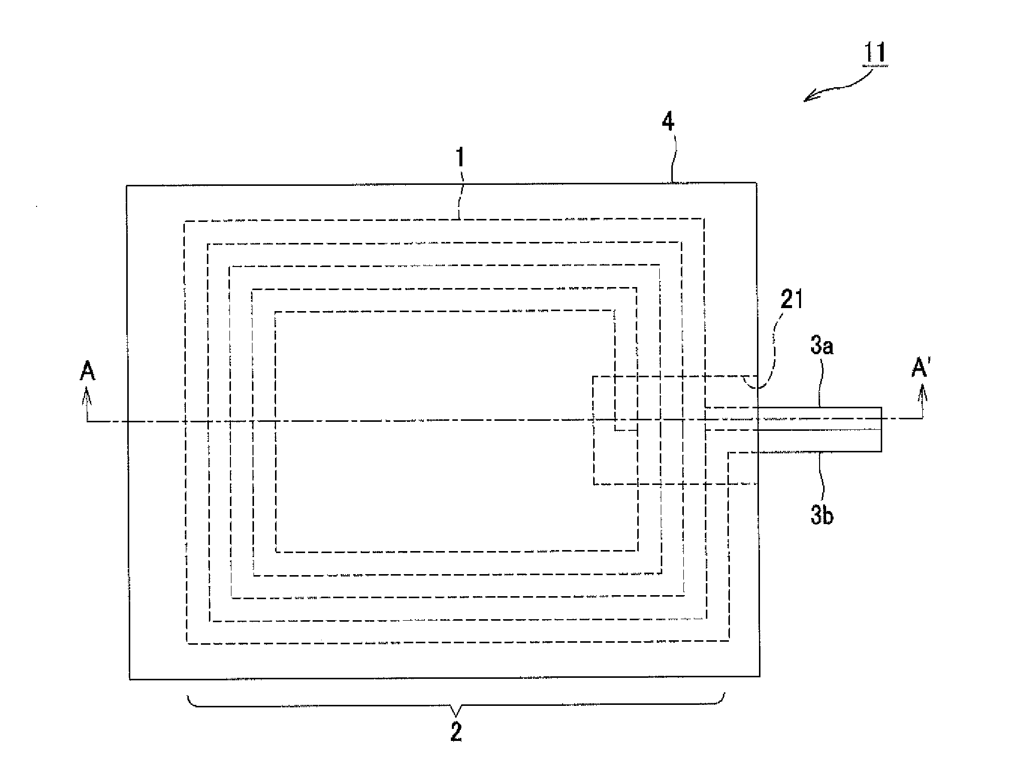
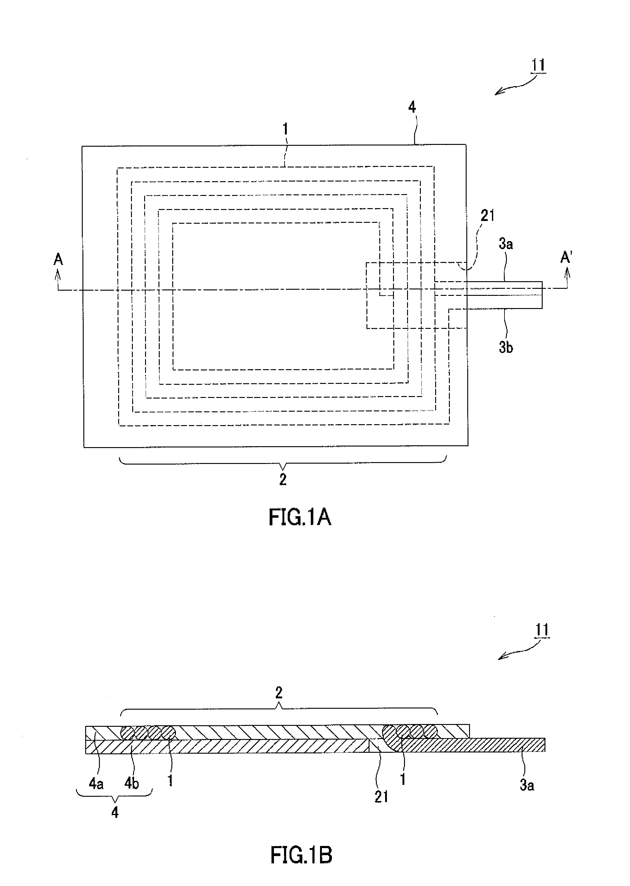
[0019]As shown in FIGS. 1A and 1B, a coil module 11 according to a first embodiment includes a spiral coil 2, formed by winding a conductor wire 1 in a spiral pattern, and a magnetic shielding layer 4 containing a magnetic material. The spiral coil 2 has lead-out portions 3a and 3b at the ends of the conductor wire 1. By connecting a rectifier circuit or the like to the lead-out portions 3a and 3b, a secondary circuit of a non-contact charging circuit is formed. As shown in FIG. 1B, the lead-out portion 3a on the radially inner side of the spiral coil 2 passes under the conductor wire 1 being wound, and is drawn out to the radially outer side of the spiral coil 2 across the conductor wire 1. The magnetic shielding layer 4 has magnetic resin layers 4a and 4b, each made of resin containing magnetic particles. The magnetic resin layer 4b is provided with a notch 21 formed of the magnetic particle-containing resin of the magnetic resin layer 4a, and the notch...

second embodiment

Configuration of Coil Module

[0034]As shown in FIGS. 4A and 4B, a coil module 12 according to a second embodiment includes the spiral coil 2, formed by winding the conductor wire 1 in a spiral pattern, and, as the magnetic shielding layer 4 containing a magnetic material, the magnetic resin layers 4a and 4b each made of resin containing magnetic particles, and a magnetic layer 4c. The spiral coil 2 has the lead-out portions 3a and 3b at the ends of the conductor wire 1. By connecting a rectifier circuit or the like to the lead-out portions 3a and 3b, a secondary circuit of a non-contact charging circuit is formed. As shown in FIG. 4B, the lead-out portion 3a on the radially inner side of the spiral coil 2 passes under the conductor wire 1 being wound, and is drawn out to the radially outer side of the spiral coil 2 across the conductor wire 1. The magnetic resin layer 4b and the magnetic layer 4c are provided with a notch 21 formed of the magnetic particle-containing resin of the mag...


PUM


Abstract

A coil module is provided which has been reduced in size and thickness by incorporating a material and a structure resistant to magnetic saturation. The coil module includes a magnetic shielding layer containing a magnetic material, and a spiral coil. The magnetic shielding layer has a plurality of magnetic resin layers containing magnetic particles, and at least a portion of the spiral coil is buried in a portion of the magnetic resin layers. This allows a reduction in size and thickness while achieving a heat dissipation effect by the magnetic resin layers. In addition, since magnetic resin layers resistant to magnetic saturation are provided, the coil inductance changes only slightly even in an environment where a strong magnetic field is applied, and thus stable communication can be provided.

Description

TECHNICAL FIELD[0001]The present invention relates to a coil module that includes a spiral coil and a magnetic shielding layer formed of a magnetic shielding material, and more particularly, to a coil module that has a magnetic resin layer containing magnetic particles, as a magnetic shielding layer. This application claims the benefit of priority from Japanese Patent Application No. 2012-265135, filed on Dec. 4, 2012 in Japan, which is incorporated herein by reference.BACKGROUND ART[0002]Modem wireless communication devices typically incorporate a plurality of RF antennas, such as a telephone communication antenna, a GPS antenna, a wireless LAN / Bluetooth (registered trademark) antenna, and a radio frequency identification (RFID). In addition to these antennas, it is becoming increasingly common that an antenna coil for electrical power transmission is also incorporated with the advent of non-contact charging technology. Methods of electrical power transmission used in non-contact c...

Claims


Application Information

Patent Timeline
IPC IPC(8): H01F27/28H01F38/14H01F27/255H01F27/29
CPCH01F27/2885H01F27/2804H01F27/255H01F38/14H01F27/29H01Q1/40H01Q7/06H01F27/2871H01F2017/048H01F27/36H01F27/366H01F5/00
Inventor KUMURA, TATSUOKUBO, YUSUKE
Owner DEXERIALS CORP
Learn More