
Realistic Laser Acupuncture Apparatus

a laser acupuncture and laser acupuncture technology, applied in the field of realistic laser acupuncture apparatus, can solve the problems of increasing the cost, increasing the time consumption, and limiting so as to increase the applicability of the realistic laser acupuncture apparatus, eliminate limitations, and simplify the structure

Inactive Publication Date: 2015-11-19
I-SHOU UNIVERSITY
View PDF1 Cites 6 Cited by
  • Summary
  • Abstract
  • Description
  • Claims
  • Application Information

AI Technical Summary

Benefits of technology

The present invention provides a realistic laser acupuncture apparatus with simpler structure and increased applicability. It eliminates limitations and allows for easier adjustment of the laser path and alignment of lenses after manufacture. This saves time and service costs for the manufacturer. The apparatus can implement lift-thrust functions using a laser beam and a focus tunable liquid lens controlled by a control unit.

Problems solved by technology

However, some patients fear needles, and there are some contraindications of needling, such as too hungry or too full.
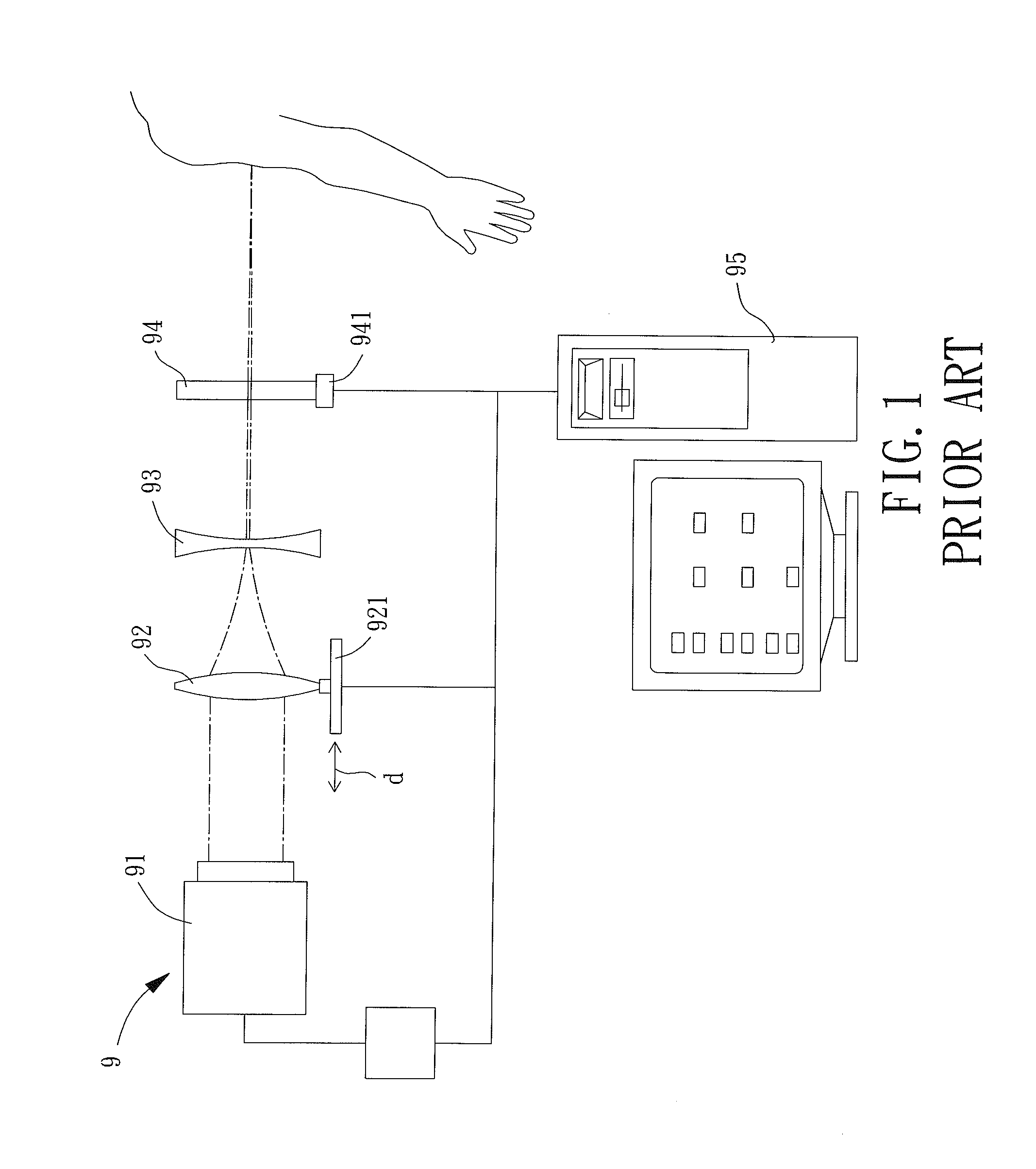
Therefore, relatively large volume was necessary, which would increase the costs and limit the applicability of the realistic acupuncture laser apparatus 9 (e.g., the realistic laser acupuncture apparatus 9 is not suitable for operation in a small space).
After-sales service for maintaining the convex lens 92 and the concave lens 93 in the predetermined locations is inevitable, which will increase the costs and time consumption.

Method used


Image

  • Realistic Laser Acupuncture Apparatus
  • Realistic Laser Acupuncture Apparatus
  • Realistic Laser Acupuncture Apparatus

Examples


first embodiment

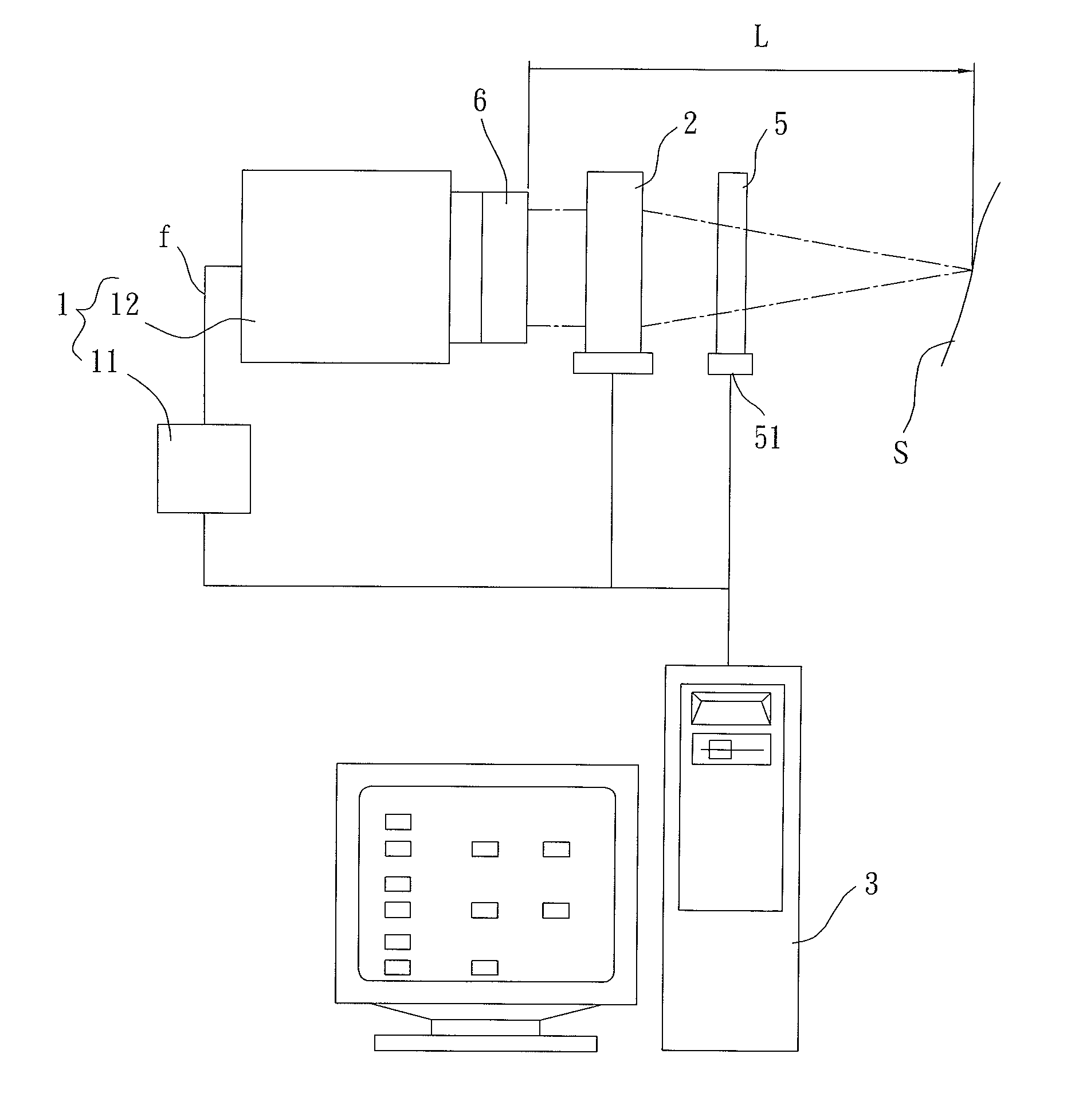
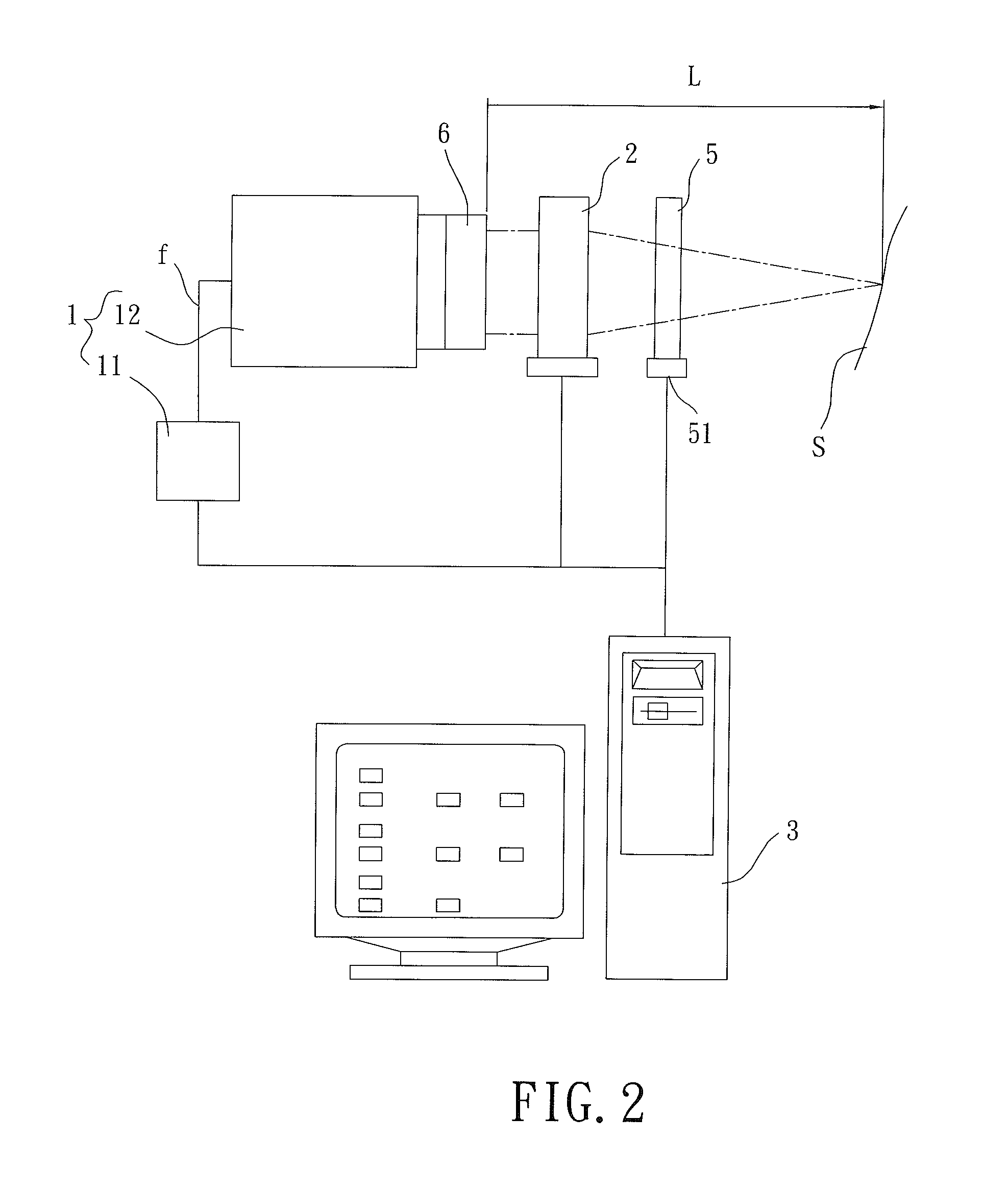
[0024]FIG. 2 is a diagrammatic view of a realistic laser acupuncture apparatus of a first embodiment according to the present invention. The realistic laser acupuncture apparatus includes a laser device 1, a focus tunable liquid lens 2, and a control unit 3. The laser device 1 generates a laser beam moving in a path L. The focus tunable liquid lens 2 is mounted in the path L of the laser beam. The control unit 3 is electrically connected to the laser device 1 and the focus tunable liquid lens 2.

[0025]The laser device 1 includes a laser driver 11 and a laser head 12 connected to the laser driver 11. Preferably, the laser driver 11 and the laser head 12 are connected by a twisted pair wire f. The laser head 12 outputs a laser beam moving along the path L to a surface S, such as a human skin. The wavelength of the laser beam is in the far infrared region (760-1000 nm). As an example, the wavelength of the laser beam can be 808 nm, because the laser beam in the far infrared region can p...

second embodiment

[0029]FIG. 3 is a diagrammatic, partly-sectioned view of a realistic laser acupuncture apparatus of a second embodiment according to the present invention. In this embodiment, the realistic laser acupuncture apparatus further includes a casing 4 having a first end 41 and a second end 42 opposite to the first end 41. The second end 42 of the casing 4 includes an opening 421.

[0030]The casing 4 includes a receiving space 43 in communication with the opening 421. Preferably, the second end 42 of the casing 4 includes an adhering portion 422 located around the opening 421, allowing the casing 4 to be adhered to a surface. In this embodiment, the laser head 12 and the focus tunable liquid lens 2 are received in the receiving space 43, with the focus tunable liquid lens 2 located between the second end 42 of the casing 4 and the laser head 12. Preferably, a polarizer 5 is mounted between the focus tunable liquid lens 2 and the second end 42 of the casing 4. The polarizer 5 is connected to ...


PUM


Abstract

A realistic laser acupuncture apparatus includes a laser device having a laser driver and a laser head. The laser head emits a laser beam moving along a path. A focus tunable liquid lens is located in the path of the laser beam. A control unit is electrically connected to the laser device and the focus tunable liquid lens. This can substantially decrease the volume and increase the applicability of the realistic laser acupuncture apparatus.

Description

BACKGROUND OF THE INVENTION[0001]1. Field of the Invention[0002]The present invention relates to a realistic laser acupuncture apparatus and, more particularly, to a realistic laser acupuncture apparatus having a simple structure and a small volume.[0003]2. Description of the Related Art[0004]Acupuncture therapy originates from China and is an alternative therapy having a long history. Acupuncture includes needling and moxibustion. Needling includes inserting needles made of silver or stainless steel into acupoints of a patient to provide a therapeutic effect while the patient feels sore, pain, or numbness. A doctor can use lifting-thrusting technique or twirling technique to apply the needles into the acupoints to a required depth according to the body condition of the patient.[0005]Traditional acupuncture is an invasive treating method. However, some patients fear needles, and there are some contraindications of needling, such as too hungry or too full. In recent years, some reali...

Claims


Application Information

Patent Timeline
Patent Type & Authority Applications(United States)
IPC IPC(8): A61N5/06
CPCA61N5/0619A61H2039/005A61N2005/067A61N2005/065A61N2005/0626A61N2005/0664A61N2005/066A61N2005/0643A61B2018/20351A61B2018/20355A61N5/067
Inventor WANG, CHIH-YUCHANG, SHU-CHENKUO, CHE-CHANG
Owner I-SHOU UNIVERSITY
Learn More