Substrate and Patterning Device for Use in Metrology, Metrology Method and Device Manufacturing Method

a metrology and patterning technology, applied in the field of metrology methods and apparatuses, can solve the problems of increasing the tightness of overlay specifications, affecting the accuracy of overlay measurement results, and the method being made with optical wavelengths, so as to improve the accuracy

Active Publication Date: 2015-11-19
ASML NETHERLANDS BV
View PDF11 Cites 30 Cited by
  • Summary
  • Abstract
  • Description
  • Claims
  • Application Information

AI Technical Summary

Benefits of technology

[0010]The invention aims to enable the use of small target metrology to measure parameters for example at locations within product areas on a semiconductor substrate, while improving the accuracy with which those measurements represent parameters of product features.

Problems solved by technology

As technology develops, however, overlay specifications become ever tighter.
One limitation of current methods is that they are made with optical wavelengths, for which the dimensions of target features are necessarily made much greater than the typical dimensions of real product features.
Consequently, the overlay measurement results from optical targets are not directly representative of overlay within the product features.
Unfortunately, for wavelengths shorter than around 200 nm, the product materials are not transparent anymore, and the instrument would not be able to “see” the bottom grating.
Unfortunately, T-SAXS signals tend to be very weak, especially when the target size is small.
Therefore the measurements tend to be too time-consuming for use in high-volume manufacturing.
Unfortunately, the small target size requires a small spot size and consequently even longer measurement times.

Method used


Image

  • Substrate and Patterning Device for Use in Metrology, Metrology Method and Device Manufacturing Method
  • Substrate and Patterning Device for Use in Metrology, Metrology Method and Device Manufacturing Method
  • Substrate and Patterning Device for Use in Metrology, Metrology Method and Device Manufacturing Method

Examples


Embodiment Construction

[0046]Before describing embodiments of the invention in detail, it is instructive to present an example environment in which embodiments of the present invention may be implemented.

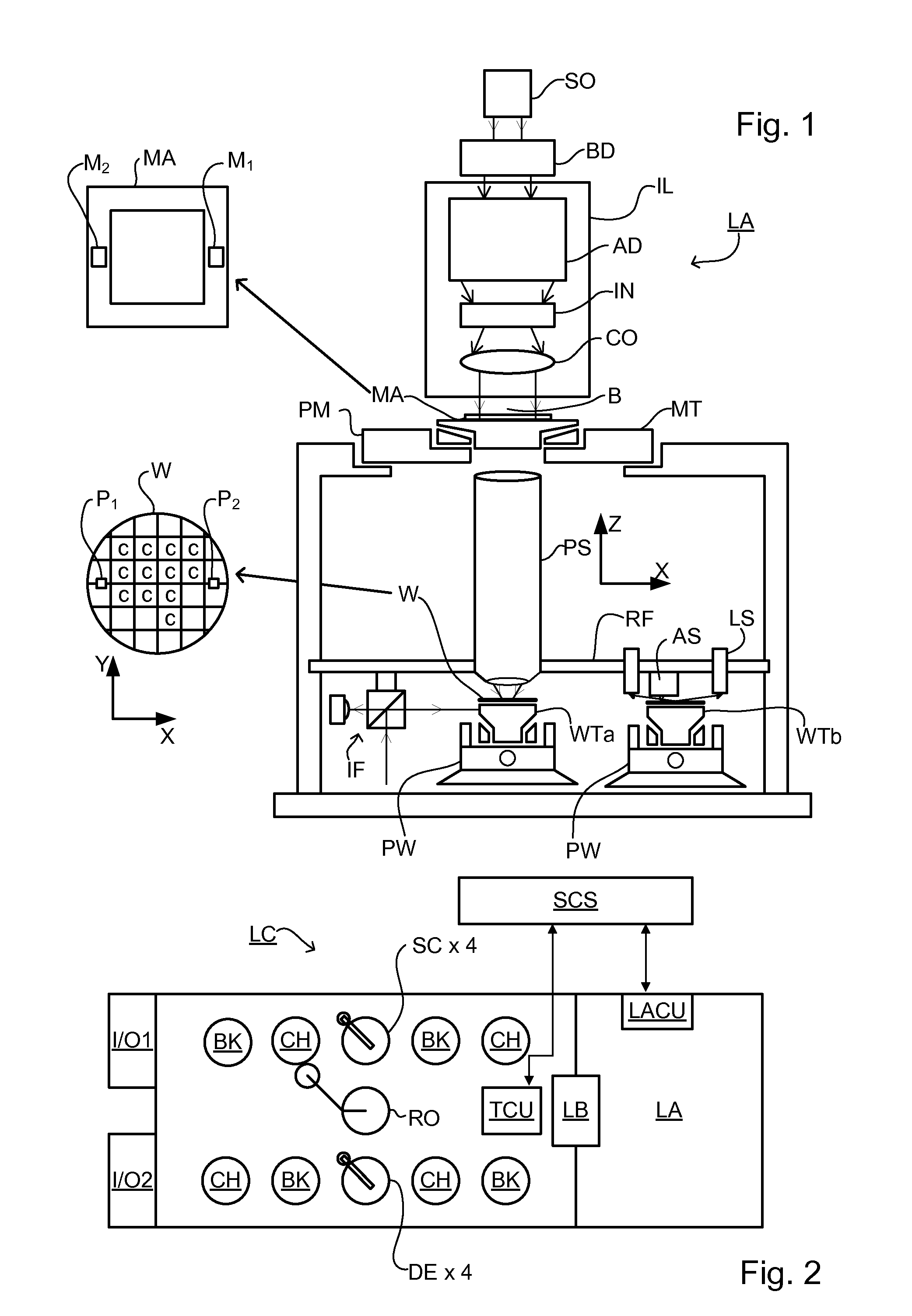
[0047]FIG. 1 schematically depicts a lithographic apparatus LA. The apparatus includes an illumination system (illuminator) IL configured to condition a radiation beam B (e.g., UV radiation or DUV radiation), a patterning device support or support structure (e.g., a mask table) MT constructed to support a patterning device (e.g., a mask) MA and connected to a first positioner PM configured to accurately position the patterning device in accordance with certain parameters; two substrate tables (e.g., a wafer table) WTa and WTb each constructed to hold a substrate (e.g., a resist coated wafer) W and each connected to a second positioner PW configured to accurately position the substrate in accordance with certain parameters; and a projection system (e.g., a refractive projection lens system) PS configured t...


PUM

PropertyMeasurementUnit
wavelengthaaaaaaaaaa
radiation of wavelengthaaaaaaaaaa
sizeaaaaaaaaaa

Abstract

A pattern from a patterning device is applied to a substrate by a lithographic apparatus. The applied pattern includes product features and metrology targets. The metrology targets include large targets which are for measuring overlay using X-ray scattering and small targets which are for measuring overlay by diffraction of visible radiation. Some of the smaller targets are distributed at locations between the larger targets, while other small targets are placed at the same locations as a large target. By comparing values measured using a small target and large target at the same location, parameter values measured using all the small targets can be corrected for better accuracy. The large targets can be located primarily within scribe lanes while the small targets are distributed within product areas.

Description

BACKGROUND[0001]1. Field of the Invention[0002]The present invention relates to methods and apparatus for metrology usable, for example, in the manufacture of devices by lithographic techniques and to methods of manufacturing devices using lithographic techniques. Methods of measuring overlay are described, as a particular application of such metrology.[0003]2. Background Art[0004]A lithographic apparatus is a machine that applies a desired pattern onto a substrate, usually onto a target portion of the substrate. A lithographic apparatus can be used, for example, in the manufacture of integrated circuits (ICs). In that instance, a patterning device, which is alternatively referred to as a mask or a reticle, may be used to generate a circuit pattern to be formed on an individual layer of the IC. This pattern can be transferred onto a target portion (e.g., including part of, one, or several dies) on a substrate (e.g., a silicon wafer).[0005]In lithographic processes, it is desirable f...

Claims


Application Information

Patent Timeline
Patent Type & Authority Applications(United States)
IPC IPC(8): G03F7/20
CPCG03F7/70683G03F7/70633G03F1/84G03F7/70483
Inventor QUINTANILHA, RICHARDCOENE, WILLEM MARIE JULIA MARCEL
Owner ASML NETHERLANDS BV
Why Eureka
Try Eureka