Non-contact power transmission system

a power transmission system and non-contact technology, applied in the direction of transformers/inductance details, transformers, inductances, etc., can solve the problem of strong and achieve the effect of reducing the leakage magnetic field into the environment and reducing the leakage magnetic flux into the environmen

Inactive Publication Date: 2015-11-19
PANASONIC INTELLECTUAL PROPERTY MANAGEMENT CO LTD
View PDF0 Cites 8 Cited by
  • Summary
  • Abstract
  • Description
  • Claims
  • Application Information

AI Technical Summary

Benefits of technology

[0009]With this configuration, most of the magnetic flux diffusing horizontally from the end of the first coil (i.e., along the winding axis of the first coil) can be oriented by the second coil upward (i.e., toward the power transmitting / receiving coil that faces the second coil), thereby reducing a leakage magnetic flux into the environment.
[0010]According to the present disclosure, the second coil orients most of the magnetic flux diffusing from the end of the first coil toward the power transmitting / receiving coil that faces the second coil, thereby reducing a leakage magnetic field into the environment.

Problems solved by technology

In particular, an intense magnetic flux diffuses to the vicinity of an end of the core, thereby causing the problem of an even stronger leakage magnetic field into the environment.

Method used


Image

  • Non-contact power transmission system
  • Non-contact power transmission system
  • Non-contact power transmission system

Examples


embodiments

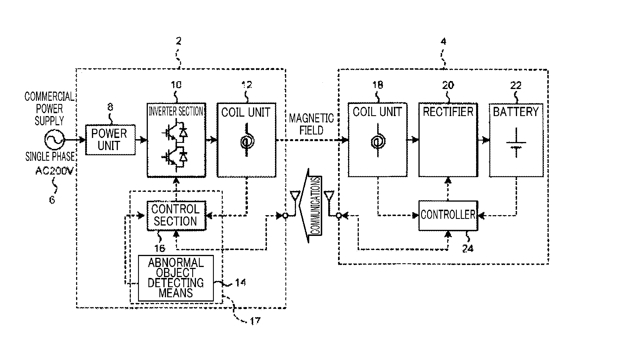
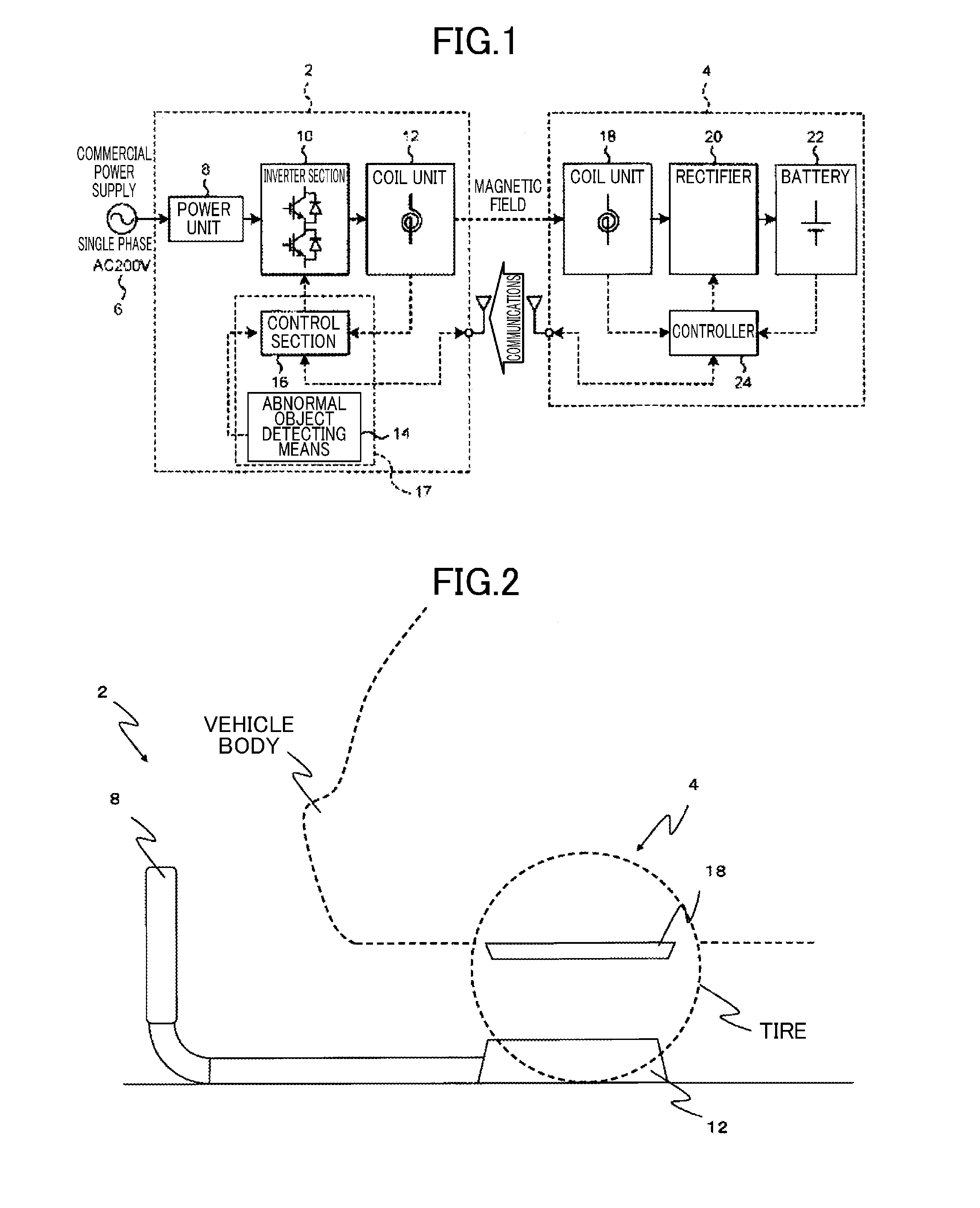
[0020]FIG. 1 is a block diagram of a non-contact power transmission system according to an embodiment of the present disclosure. FIG. 2 illustrates the appearance of the non-contact power transmission system when a vehicle is parked in a parking space.

[0021]As shown in FIGS. 1 and 2, the non-contact power transmission system includes, for example, a power supplier 2 in a parking space, and a power receiver 4 mounted on an electric propulsion vehicle.

[0022]The power supplier 2 includes a power unit 8, an inverter section 10, a ground-side coil unit (i.e., a power transmitting coil) 12, and a supplier-side controller (e.g., a microcomputer) 16. The power unit 8 is connected to a commercial power supply 6. The supplier-side controller 16 functions as a power control section 17. On the other hand, the power receiver 4 includes a vehicle-side coil unit (i.e., a power receiving coil) 18, a rectifier 20, a battery 22 as a load, and a receiver-side controller (e.g., a microcomputer) 24.

[002...


PUM

PropertyMeasurementUnit
electric poweraaaaaaaaaa
currentsaaaaaaaaaa
magnetic forceaaaaaaaaaa

Abstract

A non-contact power transmission system according to the present disclosure includes a power transmitting coil and a power receiving coil facing the power transmitting coil. At least one of the power transmitting coil and the power receiving coil includes a first coil in which a wire is wound around a first core, and a second coil in which a wire is wound around a second core. The second coil is placed at at least one end of a winding axis of the first coil. A winding axis of the second coil is inclined with respect to the winding axis of the first coil toward the power transmitting or receiving coil that faces the second coil.

Description

CROSS-REFERENCE TO RELATED APPLICATIONS[0001]This is a continuation of International Application No. PCT / JP2014 / 000444 filed on Jan. 29, 2014, which claims priority to Japanese Patent Application No. 2013-015070 filed on Jan. 30, 2013. The entire disclosures of these applications are incorporated by reference herein.BACKGROUND[0002]The present disclosure relates to non-contact power transmission systems for charging, for example, electric propulsion vehicles such as electric vehicles and plug-in hybrid vehicles.[0003]Japanese Patent Publication No. 2010-172084 discloses a conventional power transmitting coil or power receiving coil for a non-contact power transmission system. The coil includes a plurality of cores arranged at some intervals. The plurality of cores output lines of magnetic force filling gaps between themselves. Thus, those cores together function as a single core with an enlarged size, because the overall size of the core includes the sizes of the gaps. This feature ...

Claims


Application Information

Patent Timeline
Patent Type & Authority Applications(United States)
IPC IPC(8): H01F38/14H01F5/02H02J5/00
CPCH01F38/14H01F5/02H02J5/005H01F27/2823H01F27/38H02J50/10H02J50/70
Inventor OMORI, YOSHIHARUBESSYO, DAISUKEFUJITA, ATSUSHISADAKATA, HIDEKIKURIHARA, HIROAKI
Owner PANASONIC INTELLECTUAL PROPERTY MANAGEMENT CO LTD
Why Eureka
Try Eureka