Rotary electric machine

a rotary electric machine and electric motor technology, applied in the direction of association with control/drive circuits, electrical apparatus contruction details, association with printed circuit non-printed electric components, etc., can solve the problem of insensitivity of machines, and achieve the effect of minimizing the emission of electromagnetic signals and being effective and efficien

Active Publication Date: 2015-11-19
BROSE FAHRZEUGTEILE GMBH & CO KG HALLSTADT (DE)
View PDF4 Cites 31 Cited by
  • Summary
  • Abstract
  • Description
  • Claims
  • Application Information

AI Technical Summary

Benefits of technology

[0007]It is accordingly an object of the invention to provide a rotary electrical machine which overcomes the above-mentioned and other disadvantages of the heretofore-known devices and methods of this general type and of the invention is to provide a rotating electrical machine that is shielded in a particularly effective and efficient manner in order to minimize the emission of electromagnetic signals. In addition, the machine is to be as insensitive as possible with respect to voltage surges or rather voltage arcs.

Problems solved by technology

In addition, the machine is to be as insensitive as possible with respect to voltage surges or rather voltage arcs.

Method used


Image

  • Rotary electric machine
  • Rotary electric machine
  • Rotary electric machine

Examples


Embodiment Construction

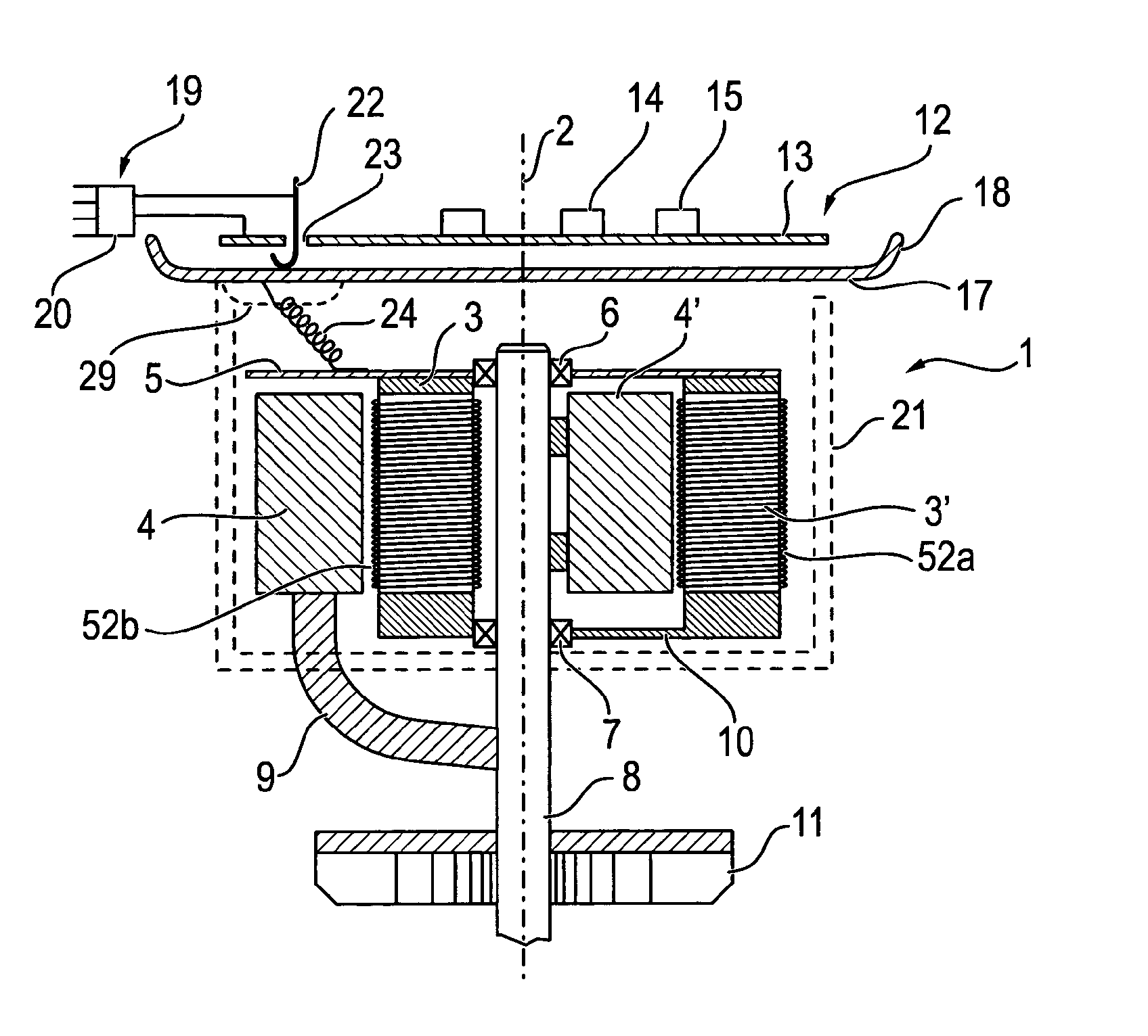
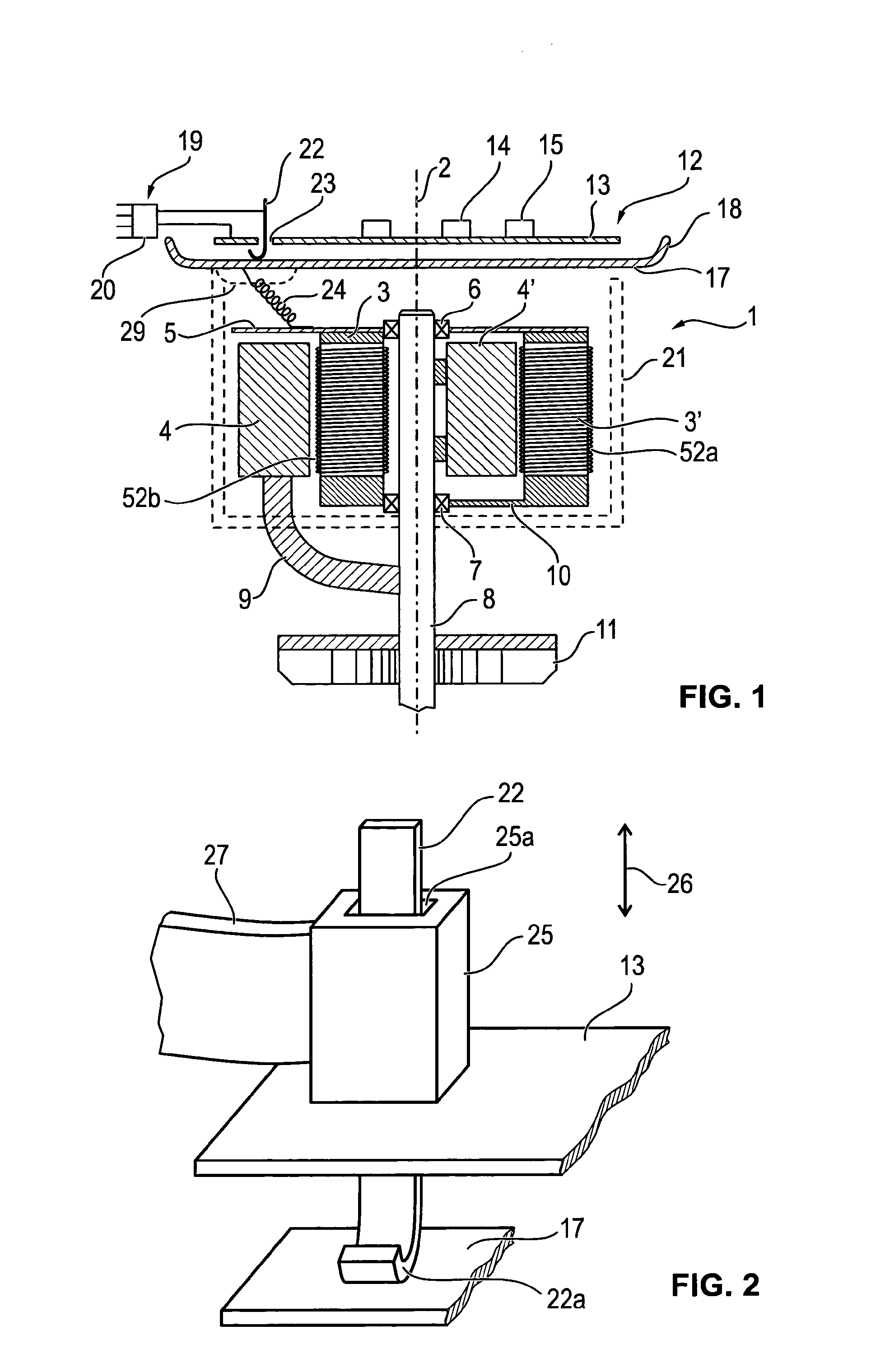
[0064]Referring now to the figures of the drawing in detail and first, particularly, to FIG. 1 thereof, there is shown, as an exemplary embodiment of the electrical machine, a longitudinal section of a brushless electric motor 1.

[0065]Different configurations are illustrated on the left-hand side and the right-hand side of a center line 2. A brushless electric motor having an inner-lying stator 3 and an outer rotor 4 are illustrated on the left-hand side in a half section. The inner-lying stator is connected to a bearing plate 5 on the front end face. A shaft 8 is mounted in a rotatable manner with respect to the bearing plate by means of a first bearing 6 and a second bearing 7 that can be embodied as identical in each case in the left-hand side half section and the right-hand side half section.

[0066]In the case of the machine that is illustrated in the left-hand side half section, the outer rotor 4 is connected to the shaft 8 by means of connecting pieces or a bell-shaped device 9...


PUM


Abstract

A rotary electric machine, in particular an electric motor, has a winding, an electronic control device, and an electrically conductive shielding plate arranged between the control device and the winding. A connection device which includes at least one coupling element for electrically connecting the control device to one or more lines and a mass element provided for connecting to an electric mass potential. In order to improve the machine with respect to electromagnetic interference, the shielding plate is electrically conductively connected to the mass element by way of a sheet metal tongue via a first electric pressure-contact.

Description

CROSS-REFERENCE TO RELATED APPLICATION[0001]This application is a continuation, under 35 U.S.C. §120, of copending international application No. PCT / EP2014 / 000190, filed Jan. 24, 2014, which designated the United States; this application also claims the priority, under 35 U.S.C. §119, of German patent application No. DE 10 2013 001 339.9, filed Jan. 26, 2013; the prior applications are herewith incorporated by reference in their entirety.BACKGROUND OF THE INVENTIONField of the Invention[0002]The invention lies in the field of electrical engineering and relates specifically to rotary electrical machines, such as electric motors and generators.[0003]Electric motors are increasingly being used in automotive technology but also in other fields of technology where increasing numbers of electrical drive units are being introduced so as to increase reliability or comfort. Often, so-called brushless motors are used as electric motors, wherein the brushless motors can be controlled in a part...

Claims


Application Information

Patent Timeline
Patent Type & Authority Applications(United States)
IPC IPC(8): H02K5/22H05K1/02H02K11/00
CPCH02K5/225H05K1/0213H02K11/0073H02K11/0005H02K2211/03H05K1/18H05K3/325H05K3/4015H05K3/4046H05K2201/10303H02K11/40H02K11/33H02K11/0141
Inventor BERKOUK, MAURADLABAT, SEBASTIENFOURNIER, ERIC
Owner BROSE FAHRZEUGTEILE GMBH & CO KG HALLSTADT (DE)
Why Eureka
Try Eureka