Rail System, Including a Rail-Bound Vehicle Movable Along a Rail Track

a rail track and rail system technology, applied in the field of rail systems, can solve the problems of low power supply achieve the effect of reducing power surge in the initial dip into the gap region, smooth movement of the rail-bound vehicle, and high supplementary drive for

Active Publication Date: 2015-11-26
SEW-EURODRIVE GMBH & CO KG
View PDF6 Cites 0 Cited by
  • Summary
  • Abstract
  • Description
  • Claims
  • Application Information

AI Technical Summary

Benefits of technology

[0006]In one advantageous development, the pole wheel piece assembly is disposed along an uphill track segment, in particular in order to generate an additional feed force for overcoming the downgrade force. This has the advantage that a lower mass may be selected for the drive of the rail-bound vehicle and track segments in the system featuring steep gradients can be traversed nevertheless. In addition, the required power supply to the rail-bound vehicle is low and the conductor line supply may therefore be set up for correspondingly small supplies.
[0007]In one advantageous further development, each pole wheel piece assembly has pole wheel pieces driven by a motor, between which at least one gap region is provided, through which a section of the reaction part can be moved. This is advantageous insofar as the immersion of the dipping section of the reaction part may extend virtually up to the outer diameter of the shaft which is driving the pole wheel pieces. A high supplementary drive force is able to be achieved in this manner. The reaction part may be produced from metallic material. The power surge in the initial dip into the gap region is able to be reduced by the design of the reaction part. That is to say, if the dipping leg segment of the reaction part is designed to include a terminal region having a pointed angle and if it dips into the gap region via this angled region, then a very smooth movement of the rail-bound vehicle is possible.
[0008]In one advantageous development, each pole wheel piece assembly has pole wheel pieces that are driven by a motor, and a gap exists between two adjacent pole wheel pieces in each case, through which a section of the reaction part can pass. This has the advantage that multiple segments of the reaction part can be driven by multiple pole wheel pieces at the same time, so that high forces are able to be generated.
[0009]In one advantageous development, the reaction part has leg sections, and each leg section is able to be plunged into a gap region situated between two pole wheel pieces of a stationary pole wheel piece assembly, and to be moved through this gap region in the direction of the track. This has the advantage that multiple leg sections dip between the pole wheel pieces at the same time. Fitting the latter with permanent magnets on both sides makes it possible to obtain a very compact design.
[0010]In one advantageous development, the reaction part is fixed in place on the linkage of the rail-bound vehicle, and the linkage is able to be maneuvered on the rail track or on rail segments of the rail track via wheels supported on the linkage. This has the advantage that the force generated by the supplementary drive is transmitted directly to the rigidly developed linkage of the rail-bound vehicle and may be used for propelling it.
[0011]In one advantageous development, the leg segments of the reaction part and / or the gap regions are set apart from each other at regular intervals. This has the advantage that the leg segments of the reactive part are able to be spaced apart in a similar manner. Moreover, a modular development may easily be realized, in which multiple pole wheel pieces are able to be stacked one behind the other.

Problems solved by technology

In addition, the required power supply to the rail-bound vehicle is low and the conductor line supply may therefore be set up for correspondingly small supplies.

Method used


Image

  • Rail System, Including a Rail-Bound Vehicle Movable Along a Rail Track
  • Rail System, Including a Rail-Bound Vehicle Movable Along a Rail Track
  • Rail System, Including a Rail-Bound Vehicle Movable Along a Rail Track

Examples


Embodiment Construction

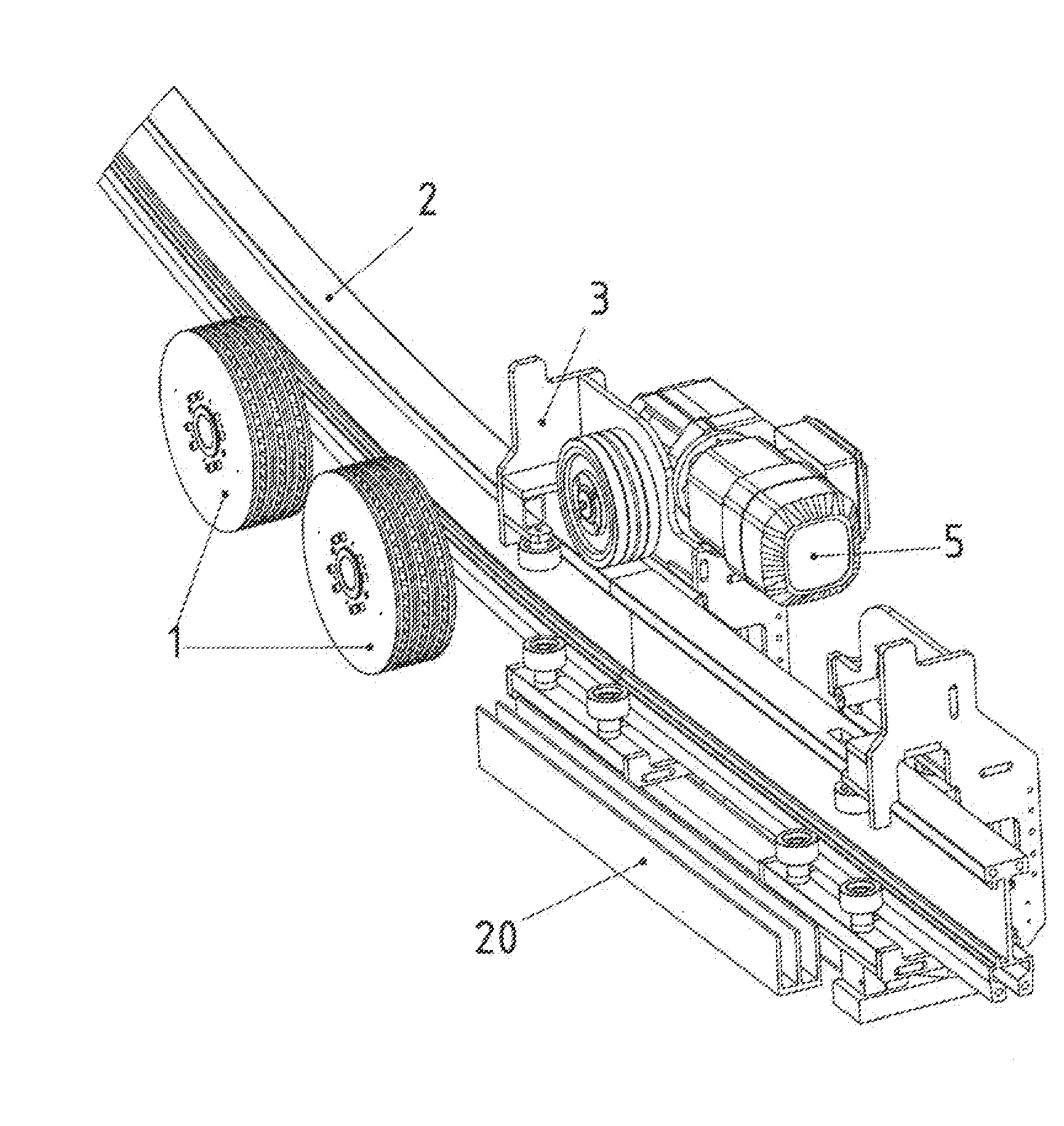
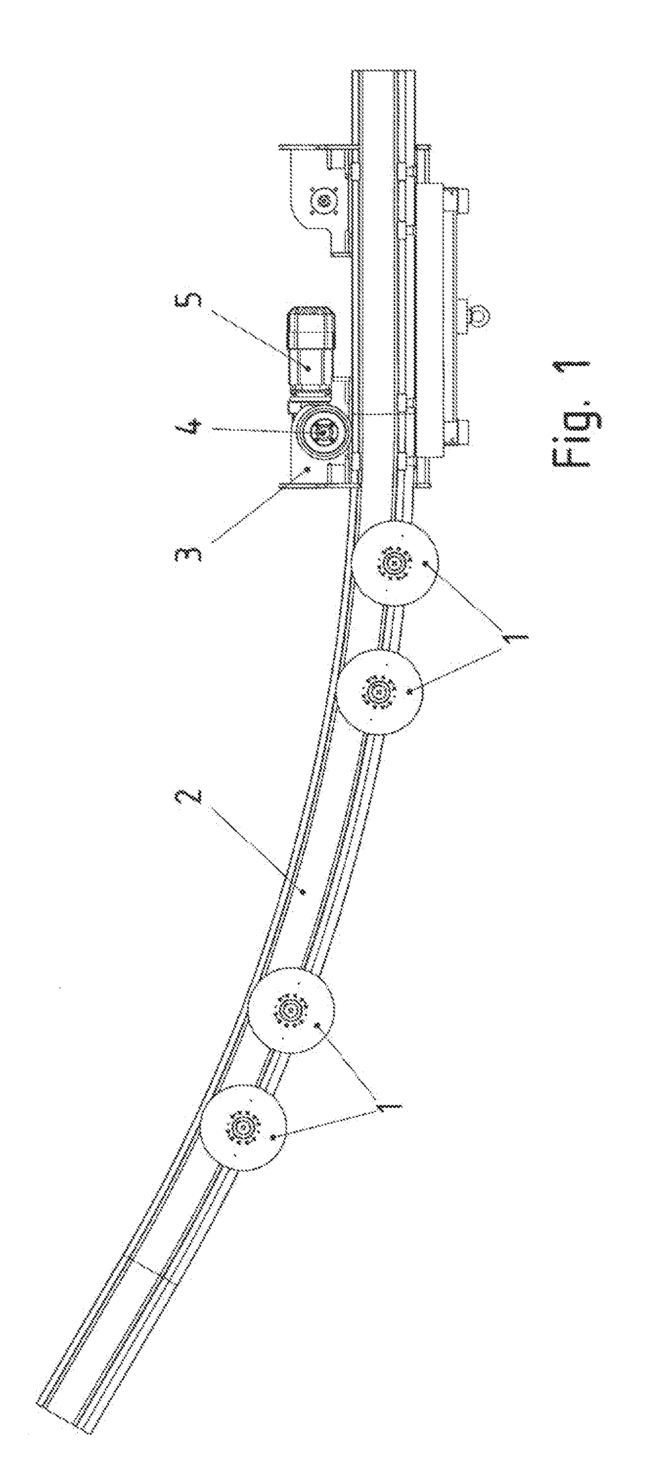
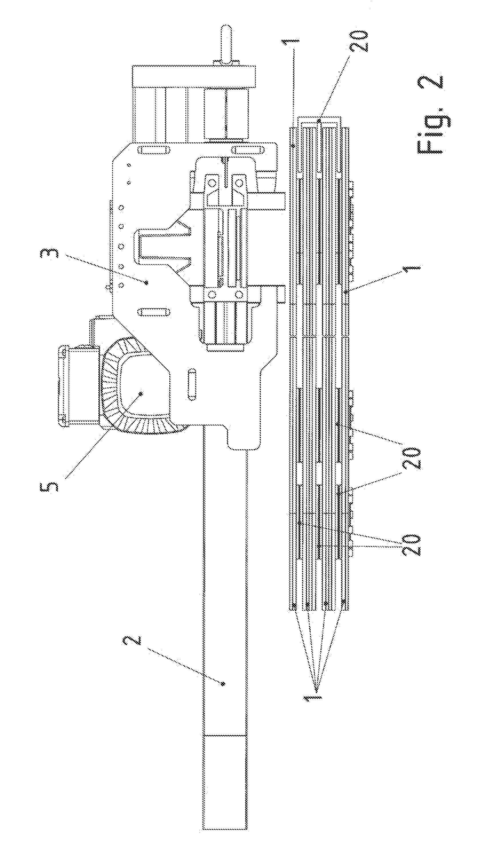
[0019]The rail system, for example, is a monorail suspension rail.

[0020]The rail-bound vehicle has a linkage 3, on which at least one drive wheel is provided, which is able to be driven by an electric motor drive. The drive wheel rolls on rail component 2 of the system and drives the rail-bound vehicle in the manner of a friction wheel drive in the process. Starting at a critical value of the drive torque of the electric motor drive, the drive wheel starts to spin because it loses traction, so that slide friction instead of static friction is active between drive wheel and rail component.

[0021]The rail track is made up of rail components 2, which are situated one behind the other. Flat, i.e., non-inclined rail track segments, i.e., in which especially no downgrade force is effective, are provided and uphill track segments as well, i.e., track segments featuring an uphill gradient, in which a downgrade force is acting.

[0022]The drive torque of the electric motor drive is dimensioned ...


PUM


Abstract

A rail system including a rail-bound vehicle, which is able to be moved along a rail track, the rail track being made up of rail components, in particular, the rail-bound vehicle having an electric motor, with the aid of which the rail-bound vehicle is able to be driven, in particular moved along the rail track in the rail direction, one or more pole wheel piece assembly/assemblies being situated in a stationary manner, i.e., connected to the rail track, the rail-bound vehicle having a reaction part, which is able to be brought into operative connection with the pole wheel piece assembly, in particular for the purpose of generating a reaction force generated by eddy currents.

Description

FIELD OF THE INVENTION[0001]The present invention relates to a rail system, which includes a rail-bound vehicle that is movable along a rail track.BACKGROUND INFORMATION It is common knowledge that rail systems include a rail-bound vehicle, which is movable along a rail track.SUMMARY[0002]Therefore, the present invention is based on the objective of further refining a rail-bound vehicle having the lowest possible mass.[0003]Important features of the present invention in the rail system, which includes a rail-bound vehicle that is movable along a rail track, in which the rail track is made up of rail components, in particular, are that the rail-bound vehicle is equipped with an electric motor, with the aid of which the rail-bound vehicle is able to be driven, especially moved, along the rail track in the track direction, one or more pole wheel piece assembly / assemblies are disposed in a stationary manner, that is to say, connected to the track, the rail-bound vehicle has a reaction p...

Claims


Application Information

Patent Timeline
Patent Type & Authority Applications(United States)
IPC IPC(8): B61B3/02B61C13/04
CPCB61C13/04B61B3/02B61B13/12
Inventor BECKER, GUNTERDEGEN, DIRK
Owner SEW-EURODRIVE GMBH & CO KG
Why Eureka
Try Eureka