Direct-current capacitor module and laminated busbar structure thereof

a direct-current capacitor and capacitor module technology, applied in the field of power electronics, can solve the problems of reducing the reliability of the power converter, reducing the voltage of the power device, and the parasitic inductance of the connective conductor, so as to reduce the parasitic inductance of the busbar structure and reduce the cost

Active Publication Date: 2015-11-26
DELTA ELECTRONICS SHANGHAI CO LTD
View PDF4 Cites 28 Cited by
  • Summary
  • Abstract
  • Description
  • Claims
  • Application Information

AI Technical Summary

Benefits of technology

[0010]The disclosure provides a direct-current (DC) capacitor module and a laminated busbar structure thereof, so as to solve aforesaid problems. The disclosure may reduce the parasitic inductance

Problems solved by technology

This traditional way is easy to implement the DC capacitors and the connective conductor layout, but the main disadvantage is that the parasitic inductance of the connective conductors will be large.
The large parasitic inductance leads the over

Method used


Image

  • Direct-current capacitor module and laminated busbar structure thereof
  • Direct-current capacitor module and laminated busbar structure thereof
  • Direct-current capacitor module and laminated busbar structure thereof

Examples


Embodiment Construction

[0031]Reference will now be made in detail to the present embodiments of the invention, examples of which are illustrated in the accompanying drawings. Wherever possible, the same reference numbers are used in the drawings and the description to refer to the same or like parts.

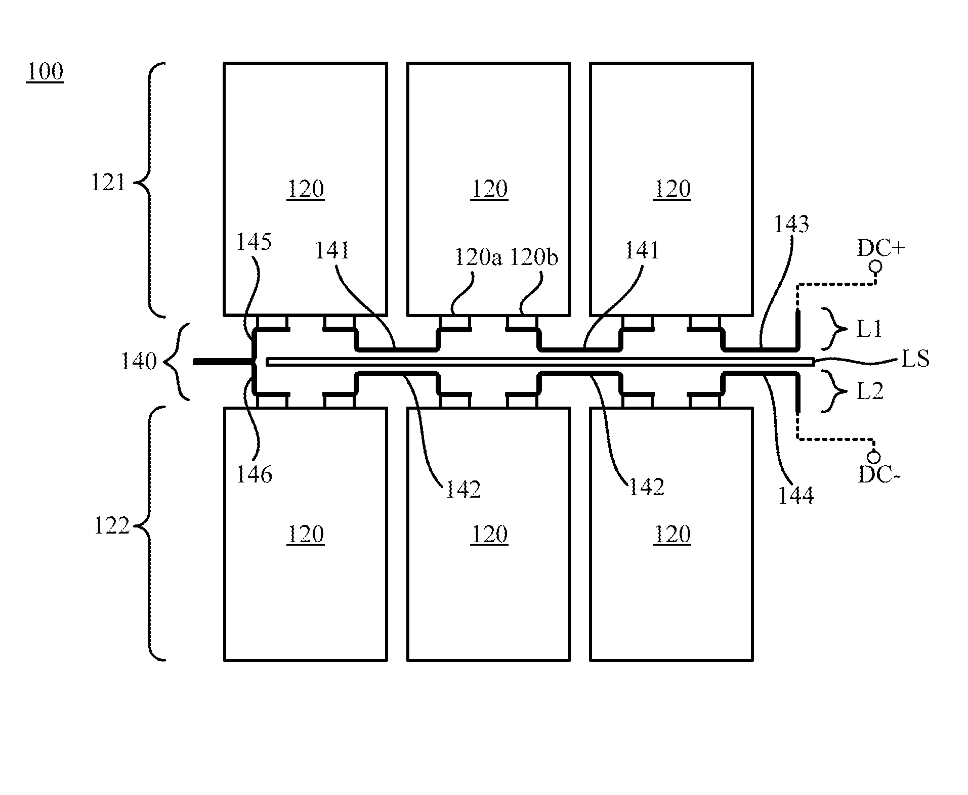
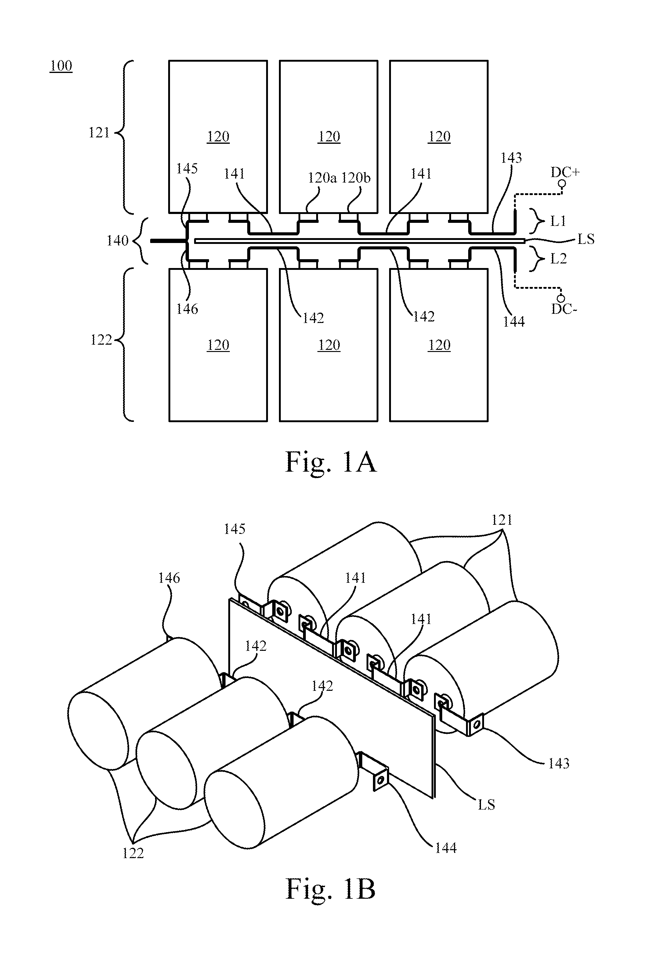
[0032]Reference is made to FIG. 1A and FIG. 1B. FIG. 1A is a sectional schematic diagram illustrating a direct-current (DC) capacitor module 100 according to an embodiment of the disclosure. FIG. 1B is an exploded diagram illustrating the direct-current capacitor module 100 in FIG. 1A from another visual angle.

[0033]As shown in FIG. 1A, the direct-current capacitor module 100 includes a plurality of direct-current capacitors 120 and a laminated busbar structure 140. For demonstration, the direct-current capacitor module 100 as shown in figures includes six direct-current capacitors 120. However, the disclosure is not limited thereto.

[0034]Each of the direct-current capacitors 120 includes two capacitor binding...


PUM


Abstract

A direct-current capacitor module is disclosed in this disclosure. The direct-current capacitor module includes a plurality of direct-current capacitors and a laminated busbar structure. The direct-current capacitors are grouped into a first portion and a second portion. The laminated busbar structure is electrically connected to capacitor binding posts of the direct-current capacitors. The laminated busbar structure has a positive terminal and a negative terminal. The laminated busbar structure includes a first busbar layer, a second busbar layer and an insulation layer. The first busbar layer includes a first sub-busbar layer, which is electrically connected between at least two direct-current capacitors of the first portion. The second busbar layer includes a second sub-busbar layer, which is electrically connected between at least two direct-current capacitors of the second portion. The insulation layer is disposed between the first busbar layer and the second busbar layer.

Description

RELATED APPLICATIONS[0001]This application claims priority to China Application Serial Number 201410222351.7, filed May 23, 2014, which is herein incorporated by reference.BACKGROUND[0002]1. Field of Invention[0003]The present invention relates to power electronics area. More particularly, the present invention relates to a direct-current capacitor module of a power converter and a laminated busbar structure thereof.[0004]2. Description of Related Art[0005]Electronic products usually require a specific voltage, a specific current or a specific power to be operated properly. Therefore, power converters are needed to transform various power inputs (e.g., power from a household electricity outlet) into signals with appropriate power specifications.[0006]A direct-current (DC) capacitor module (also known as DC-link) is an important part of the power converter. A parasitic inductance of a connective conductor of the direct-current capacitor module is closely related to an over-voltage st...

Claims


Application Information

Patent Timeline
IPC IPC(8): H01G4/38
CPCH01G4/38H02M7/003H01G2/04H01G2/06H01G4/228H05K7/14329H05K7/1432
Inventor WEN, SEN-LINYING, JIAN-PINGGAN, HONG-JIANZHAO, SHE
Owner DELTA ELECTRONICS SHANGHAI CO LTD
Why Eureka
Try Eureka