Adjustment of a capacitor charge voltage

a capacitor and charge voltage technology, applied in the direction of charge maintainance charging/discharging, electric vehicles, transportation and packaging, etc., can solve the problems of limited lifetime, capacitance and conductance decrease, and the limited lifetime of edlcs is particularly problematic, so as to prolong the lifetime of the capacitor

Inactive Publication Date: 2015-11-26
SCHNEIDER ELECTRIC BUILDINGS LLC
View PDF15 Cites 11 Cited by
  • Summary
  • Abstract
  • Description
  • Claims
  • Application Information

AI Technical Summary

Benefits of technology

[0009]The energy stored in a capacitor Wstored is proportional to the capacitance value and to the square of the voltage across the capacitor. Due to aging, the capacitance value decreases over time. Accordingly, if the charge voltage is kept constant, the energy stored in the capacitor Wstored decreases over time, and after a while the energy Wstored stored in the capacitor will be lower than the required energy level Wneed. With the method of the invention, however, the charge voltage is adjusted to compensate for the aging of the capacitor. The charge voltage is adjusted such that the energy level Wstored stored in the capacitor is kept essentially constant. Thus, as the capacitance decreases due to aging of the capacitor, the charge voltage will be increased and the energy level Wstored stored in the capacitor may be kept above the required energy level Wneed. The lifetime of the capacitor is thereby increased. Moreover, since the charge voltage at any time may be chosen to be as low as possible while still keeping the energy level stored in the capacitor at a level which exceeds the required energy level Wneed the aging of the capacitor is slowed down. Further, the time taken to charge the capacitor is in this way reduced.
[0016]The method may further comprise determining the capacitance value of the capacitor. In one embodiment, the act of determining the capacitance value of the capacitor may comprise: performing one of charging or discharging of the capacitor by providing a charging current to the capacitor, or connecting a load in parallel with the capacitor, such that thereby a discharging current is caused to flow from the capacitor, wherein the charging or discharging is initiated at a first time point; measuring a charge change of the capacitor during a time period when the capacitor is charged or discharged, wherein the time period occurs after the first time point; measuring a first voltage change across the capacitor during the same time period; and determining the capacitance value as a ratio between the measured charge change and the measured first voltage change. This is advantageous in that it enables an accurate capacitance value of the capacitance to be obtained by performing direct measurements on the capacitor.
[0019]In one embodiment, the act of receiving a capacitance value of the capacitor comprises receiving information pertaining to variation of the capacitance value as a function of time and / or temperature from a curve or a table; and determining the capacitance value of the capacitor as the capacitance value of the curve or table that corresponds to a current time and / or temperature. This is advantageous in that the capacitance value may be determined in a simple way using a low amount of processing power.

Problems solved by technology

A problem with EDLCs is that they have a limited lifetime in that the capacitance and conductance decrease due to electrochemical reactions.
The limited lifetime of the EDLCs is particularly problematic when the EDLCs are used in applications with requirements on long product lifetimes. The aging of the EDLCs is influenced by temperature and voltage.
Increasing the voltage and temperature will exponentially accelerate the electrochemical reactions and thus leading to a decrease in capacitance and conductance.
This approach is disadvantageous in that, initially, more energy is stored in the capacitor than needed.
This approach is further disadvantageous in that large capacitors are expensive and that charging of large capacitors to a high voltage level requires a larger and more expensive power supply circuit.
Further, the charging of a large capacitor is time consuming.
The solution of cooling the EDLCs to extend the lifetime as disclosed in JP2005117792 is disadvantageous in that it requires a bulky fan.
As a result, it may not be used in applications where the space is limited.
Further, fans may not be used in harsh and dusty environments.

Method used


Image

  • Adjustment of a capacitor charge voltage
  • Adjustment of a capacitor charge voltage
  • Adjustment of a capacitor charge voltage

Examples


Embodiment Construction

[0031]The present invention will now be described more fully hereinafter with reference to the accompanying drawings, in which currently preferred embodiments of the invention are shown. This invention may, however, be embodied in many different forms and should not be construed as limited to the embodiments set forth herein; rather, these embodiments are provided for thoroughness and completeness, and fully convey the scope of the invention to the skilled person.

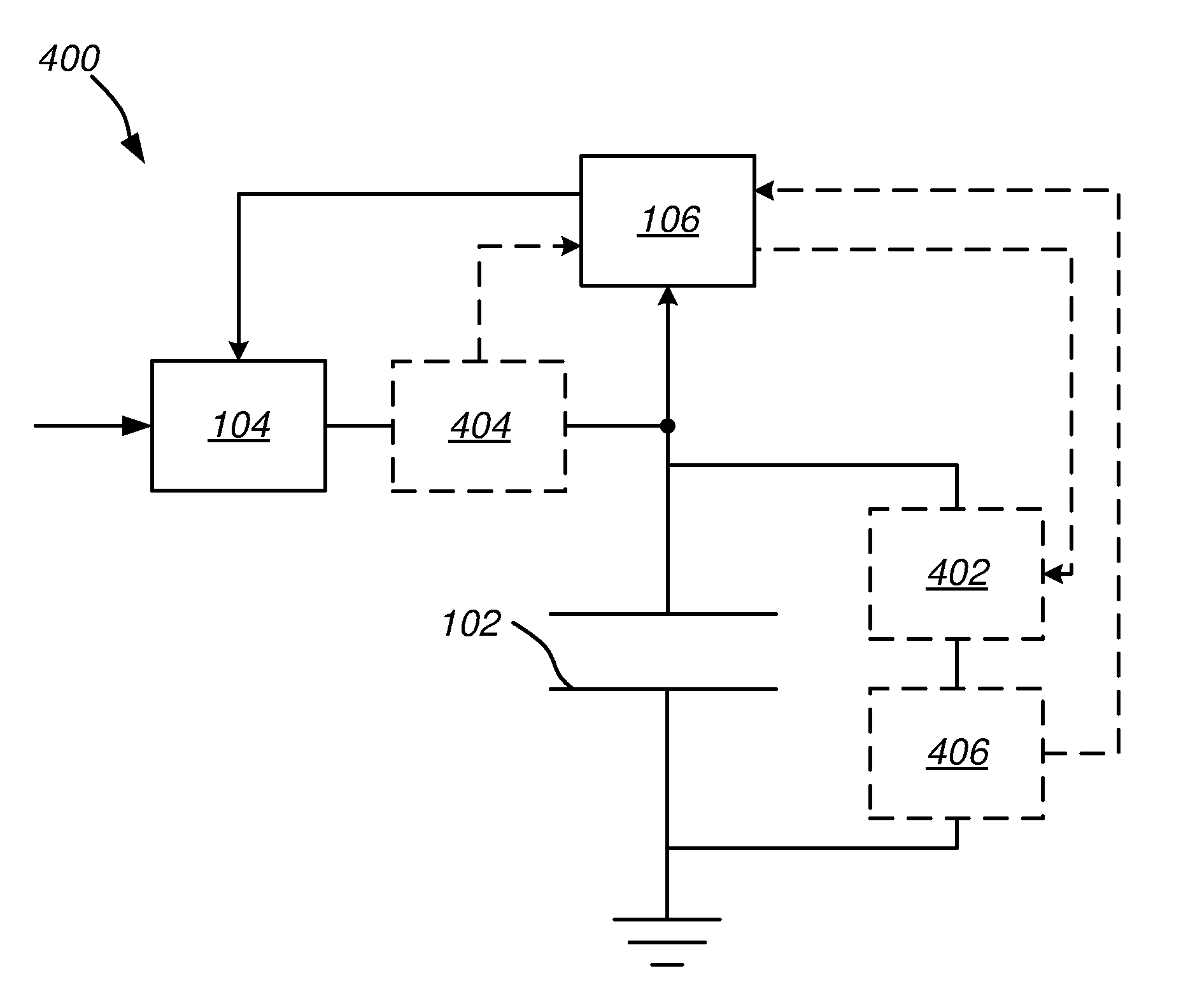
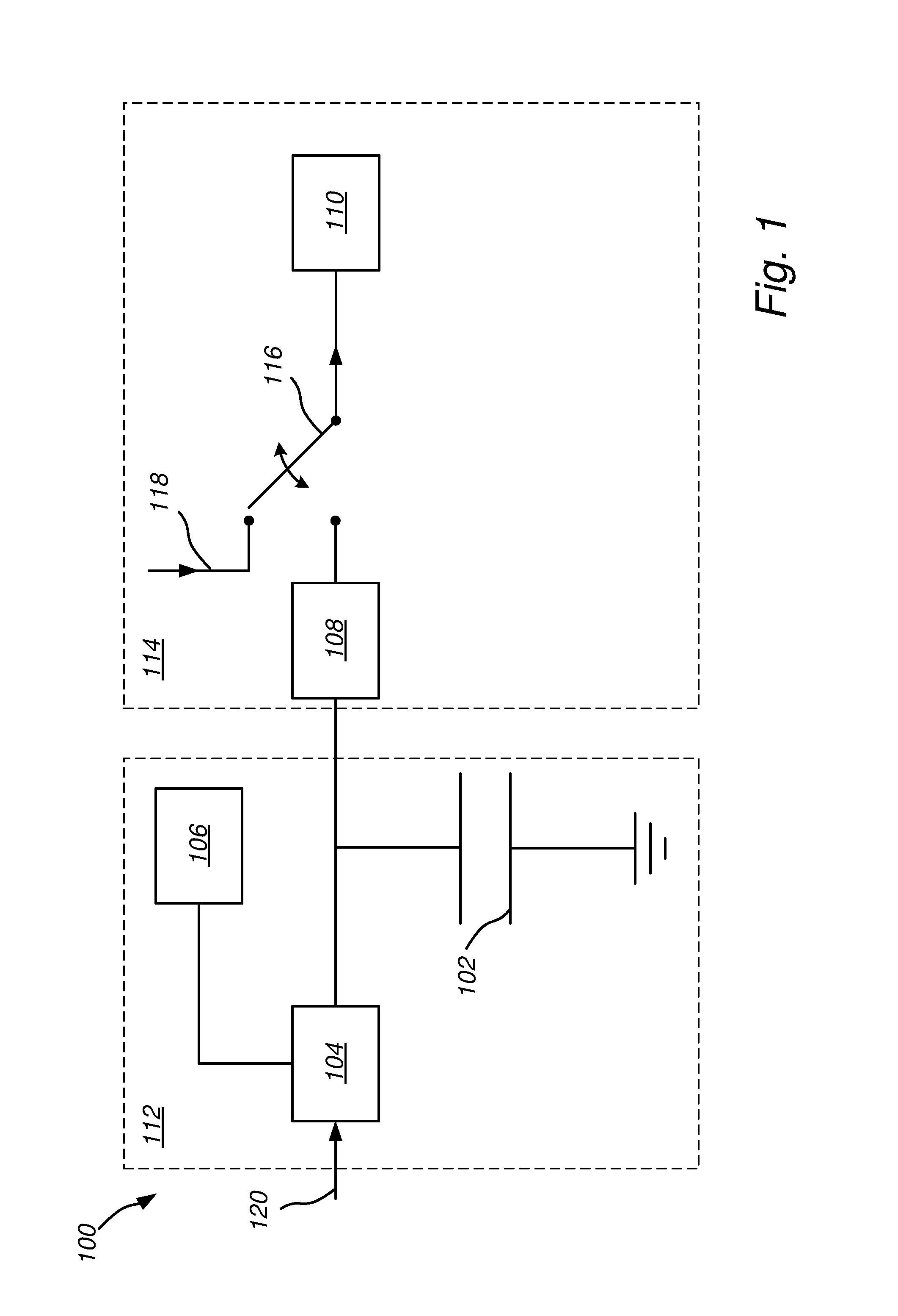
[0032]FIG. 1 illustrates a system 100 comprising a load 110 and a capacitor 102. The system 100 may be used as a back-up system for powering the load 110. Particularly, the capacitor 102 may be used as a back-up power source for the load 110. Normally, the load 110 is powered via a power net 118. However, if there is a power fail, the load may be connected to the backup-system comprising the capacitor 102, for example by means of a switch 116.

[0033]The system 100 has a charging part 112 and a discharging part 114. The disch...


PUM


Abstract

A method, a system, and a control unit for adjusting a charge voltage of a capacitor which is used as a power backup in a system having a required energy level. The method includes adjusting the charge voltage of the capacitor based on a received capacitance value and a received value of the required energy level. The energy level stored in the capacitor is kept essentially constant. The method and system are advantageous in that they extends the lifetime of the capacitor

Description

TECHNICAL FIELD[0001]The present invention generally relates to the field of charging of capacitors in systems having a charging part and a discharging part. In particular, it relates to a method and arrangements for adjusting the charge voltage of a capacitor in such systems.BACKGROUND[0002]Electrochemical double layer capacitors (EDLCs), also known as ultra capacitors or super capacitors, are often used as energy storage devices in electronic circuits. For example EDLCs may be used as a power back-up in a system.[0003]A problem with EDLCs is that they have a limited lifetime in that the capacitance and conductance decrease due to electrochemical reactions. The limited lifetime of the EDLCs is particularly problematic when the EDLCs are used in applications with requirements on long product lifetimes. The aging of the EDLCs is influenced by temperature and voltage. Increasing the voltage and temperature will exponentially accelerate the electrochemical reactions and thus leading to...

Claims


Application Information

Patent Timeline
Patent Type & Authority Applications(United States)
IPC IPC(8): H02J7/00
CPCH02J7/345H02J7/007H02J7/0069H02J7/04H02J7/00
Inventor GOTH, FREDRIK
Owner SCHNEIDER ELECTRIC BUILDINGS LLC
Why Eureka
Try Eureka