Storage subsystem and method for controlling the same
a storage subsystem and subsystem technology, applied in the direction of memory adressing/allocation/relocation, electrical apparatus casings/cabinets/drawers, instruments, etc., can solve the problem that ssd has a bit cost with respect to storage capacity that is more expensive, and achieves the effect of reducing costs, improving backend processing performance, and enhancing transfer bandwidth
- Summary
- Abstract
- Description
- Claims
- Application Information
AI Technical Summary
Benefits of technology
Problems solved by technology
Method used
Image

Examples
embodiment 1
System Configuration and Outline of Invention
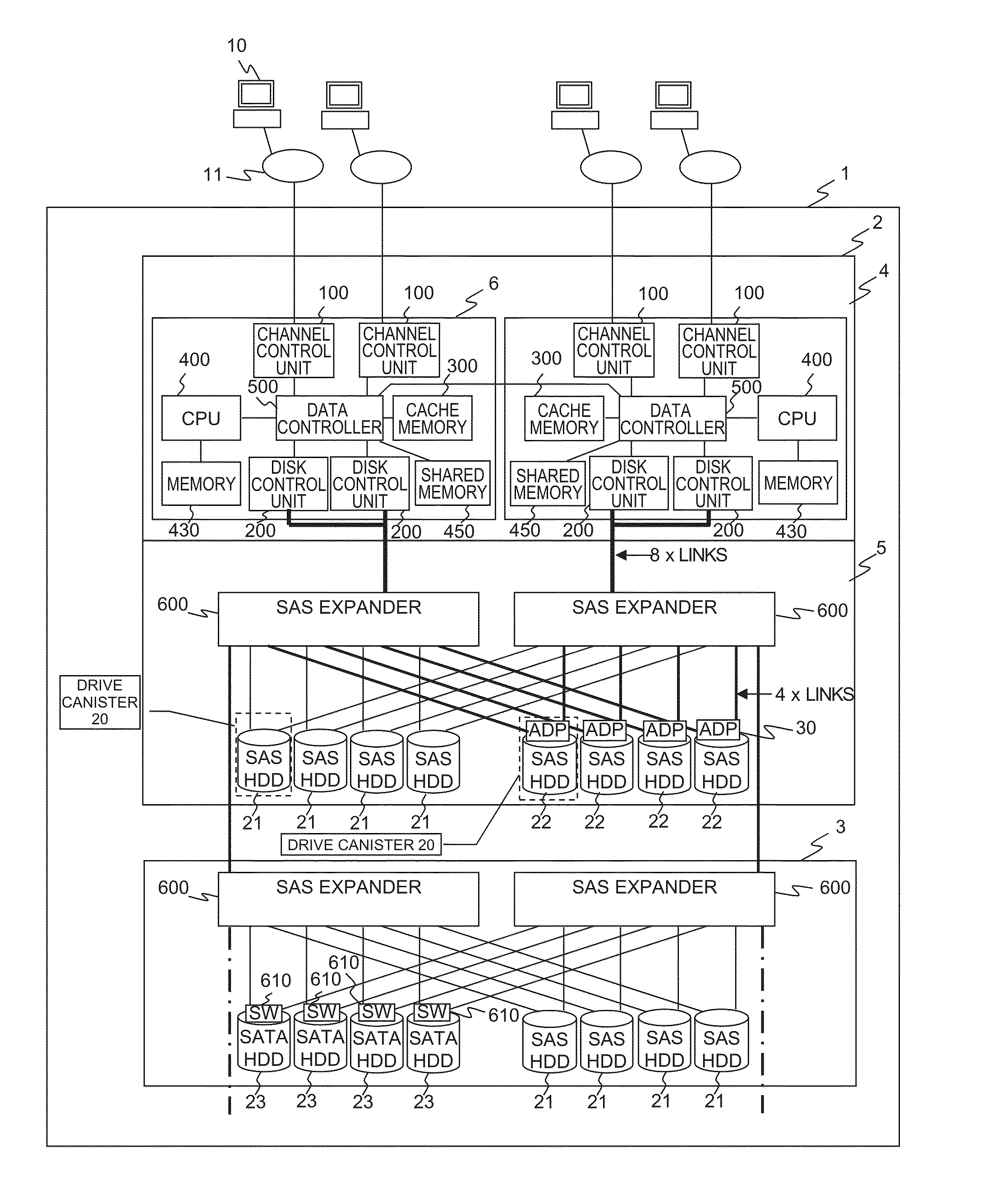
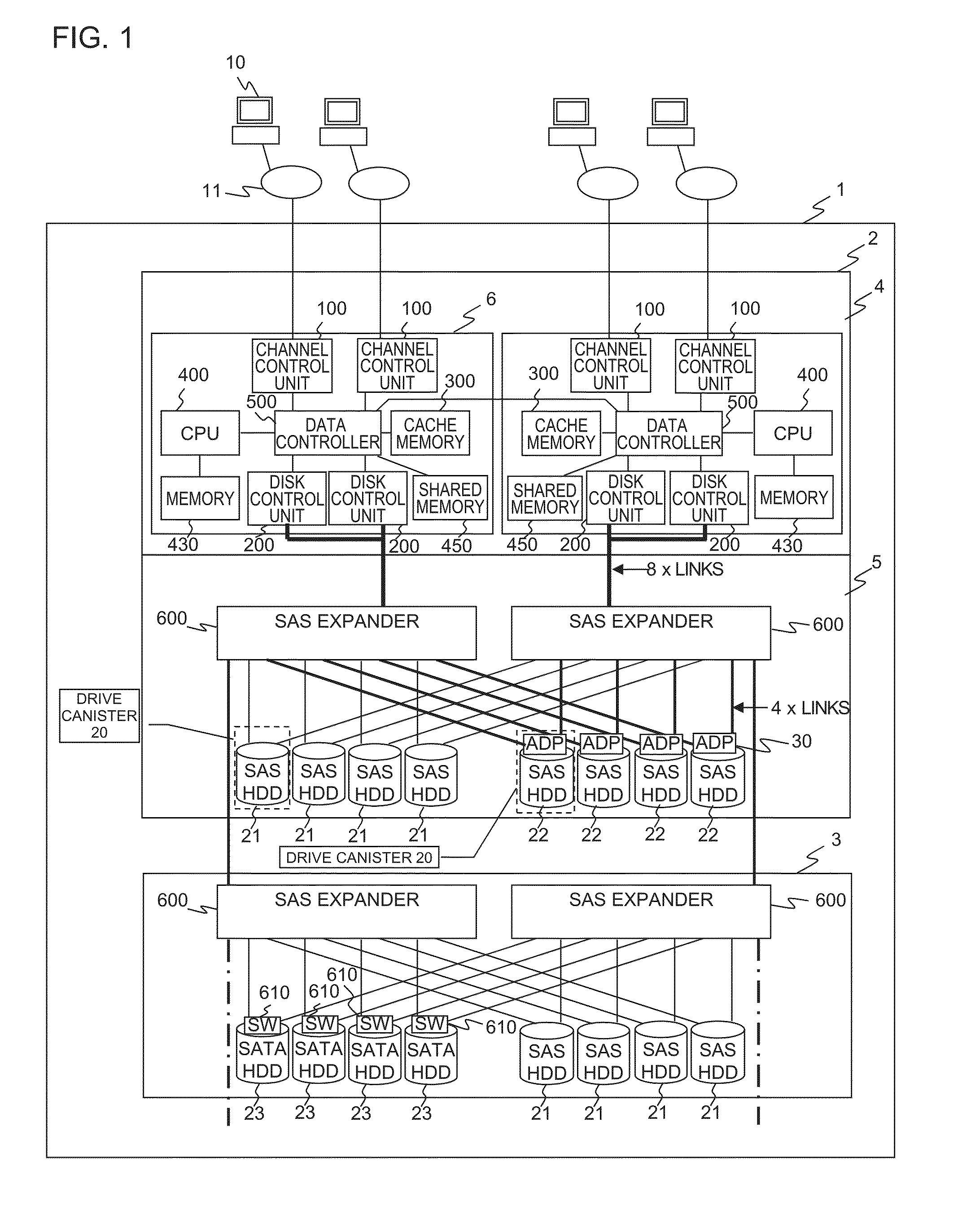
[0032]FIG. 1 is a block diagram illustrating the hardware of a storage subsystem. FIG. 1 illustrates an example where a semiconductor memory adapter board 30 is attached to a drive canister 20 mounting an HDD such as a SAS drive 22, which is a characteristic feature of the present invention. The drive canister 20 is a small-size chassis having an HDD, an SSD or a semiconductor memory built therein and coupled to a storage subsystem. Further, the semiconductor memory adapter board 30 is an adapter board capable of being coupled to the HDD and which is equipped with a semiconductor memory board having multiple semiconductor memories (rewritable nonvolatile memories such as flash memories according to the present embodiment) mounted on a printed board, and a hardware resource such as a controller (CPU, for example) for controlling the semiconductor memory board.
[0033]The storage subsystem 1 is coupled to a host computer 10 via a network 11. ...
embodiment 2
[0105]A method according to a second embodiment of the present invention will be described with reference to FIG. 11, wherein the semiconductor memory adapter boards 30 are not attached to the drive canister 20, but instead, slots are provided to allow the boards to be attached to the chassis. FIG. 11 is a view illustrating an example of attaching the semiconductor memory adapter boards 30 to the slots on the chassis. FIG. 11(1) illustrates an example where the boards are mounted to the front side of the chassis, wherein the storage drives (HDDs) and the semiconductor memory adapter boards 30 are mounted in a one-to-one relationship. FIG. 11(2) illustrates an example where the boards are mounted within the chassis, wherein the storage drives (HDDs) and the semiconductor memory adapter boards 30 are mounted in a N-to-one relationship. The eight shaded HDDs 1102 constitute a single RAID group (such as 7D+1P).
[0106]In the present embodiment, the port switching mechanism 322 is not disp...
embodiment 3
[0110]A third embodiment of the present invention aims at suppressing deterioration of performance when the semiconductor memory adapter board 30 is replaced due to failure or end of lifetime. According to the prior art, when the SSD fails or the life thereof is ended, all the data or stored data in the SSD must be restored from other SSDs in the same RAID group and copied to the spare SSD, and the replacement is performed in drive units such as HDDs and SSDs, so that the copying time for data recovery is extremely long.
[0111]Further, when the flash memory board or the SSD is used as an expanded (external) cache memory, generally the memory was used as a read cache. The reason is because in the case of a write cache operation where update data is cached regardless of access frequency, the end of lifetime of the flash memory is accelerated.
[0112]Therefore, if the total capacity of the hot spot of update data exceeds the capacity of the cache memory 300 mounted to the storage controll...
PUM
 Abstract
Description
Claims
Application Information
 - R&D
- Intellectual Property
- Life Sciences
- Materials
- Tech Scout
- Unparalleled Data Quality
- Higher Quality Content
- 60% Fewer Hallucinations
Browse by: Latest US Patents, China's latest patents, Technical Efficacy Thesaurus, Application Domain, Technology Topic, Popular Technical Reports.
© 2025 PatSnap. All rights reserved.Legal|Privacy policy|Modern Slavery Act Transparency Statement|Sitemap|About US| Contact US: help@patsnap.com