Therapeutic and diagnostic probes

a technology of diagnostic probes and probes, applied in the field of diagnostic probes, can solve the problems of lack of effective tissue localization of current photodynamic therapeutic agents

Active Publication Date: 2015-12-03
RAKUTEN MEDICAL INC
View PDF3 Cites 17 Cited by
  • Summary
  • Abstract
  • Description
  • Claims
  • Application Information

AI Technical Summary

Benefits of technology

[0008]In some embodiments, the nanocarrier further comprises a targeting agent. In some instances, the targeting agent is an antibody or frag

Problems solved by technology

Current photodynamic therapeutic agen

Method used


Image

  • Therapeutic and diagnostic probes
  • Therapeutic and diagnostic probes
  • Therapeutic and diagnostic probes

Examples


example 2

Therapeutic and Diagnostic Probes Containing a Viral Particle and a Targeting Moiety

[0096]This example provides an exemplary embodiment of the present invention, in particular, a therapeutic and diagnostic probe based on a viral particle that selectively binds to EGFR expressing cells, such as cancer cells.

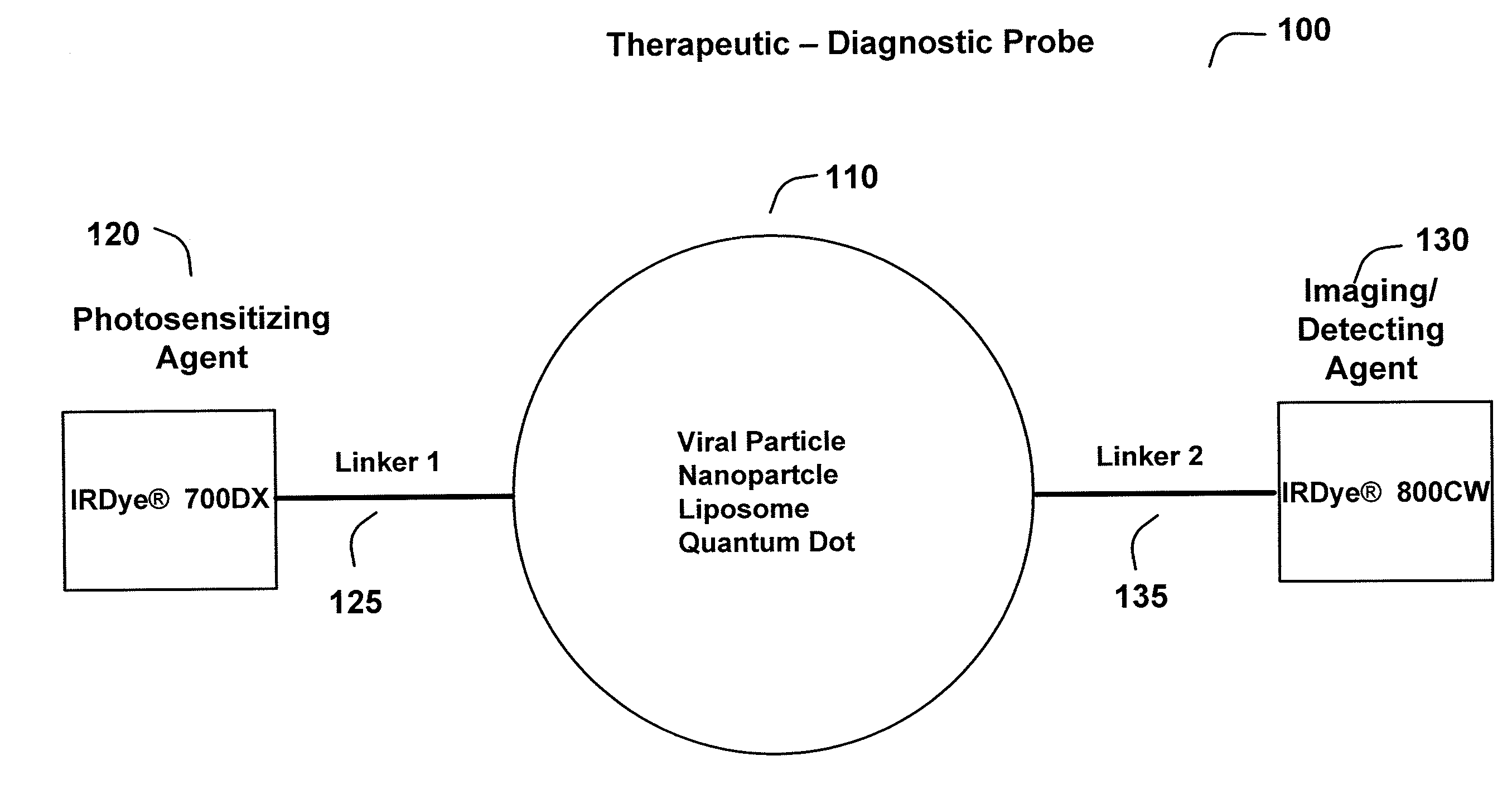
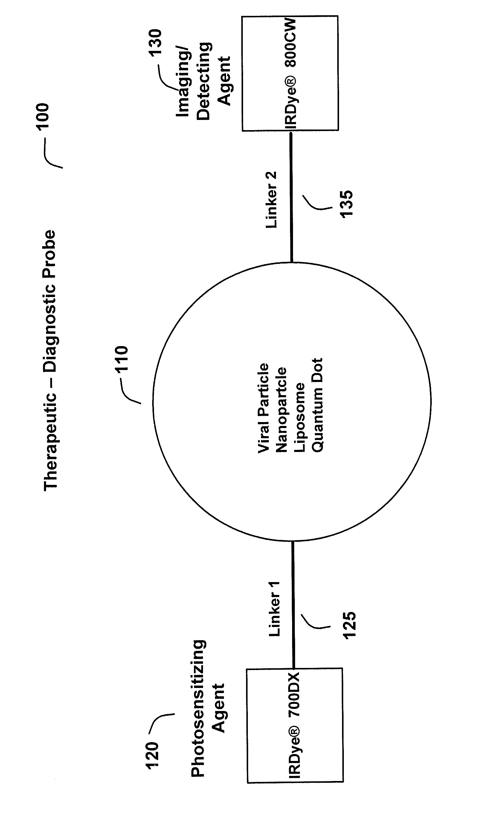
[0097]The virus-like particle based probe is generated according to the method described in Example 1 with modifications to express a targeting moiety, such as EGF on the surface of the probe. The EGF protein can be labeled on free amine groups using an NHS ester derivative of IRDye® 700DX or IRDye® 800CW (LI-COR, Lincoln, Nebr.). The viral-like particle can also be linked to the dye(s) through a linker as described above.

[0098]The probe is administered to the subject, e.g., the human subject, by intravenous injection or by direct injection into a solid tumor containing EGFR-overexpressing cells. The EGF probe then binds to EGFR on the surface of cancer cells. Near-infrared fluore...


PUM

PropertyMeasurementUnit
Cell deathaaaaaaaaaa
Therapeuticaaaaaaaaaa

Abstract

The present invention provides compositions and methods of use of nanoparticle-based probes for in vivo imaging and therapy. The probes can be used to track diseased target cells by non-invasive imaging in the near-infrared range. Additionally, the probes can induce cell death of the target cells via photodynamic treatment.

Description

CROSS-REFERENCE TO RELATED APPLICATIONS[0001]This application claims priority to U.S. Provisional Patent Application Nos. 62 / 006,790, filed Jun. 2, 2014; 62 / 017,165, filed Jun. 25, 2014; 62 / 066,807, filed Oct. 21, 2014 and 62 / 082,052, filed Nov. 19, 2014, the teachings all of which are hereby incorporated by reference in their entireties for all purposes.BACKGROUND OF THE INVENTION[0002]Photodynamic therapy (PDT) is a clinically approved and rapidly evolving treatment regimen for disease including cancer, cardiovascular disease, dermatological diseases and ophthalmic disease. PDT traditionally involves administration of a photosensitizer that preferentially accumulates within a target tissue site. Following illumination of the tissue site with light of an appropriate wavelength, in the presence of molecular oxygen, reactive oxygen species, such as singlet oxygen, free radicals and peroxides are produced which, in turn, damage cellular structures containing the photo-sensitizer. The ...

Claims


Application Information

Patent Timeline
IPC IPC(8): A61K47/48A61K49/00A61N5/06A61K41/00
CPCA61K47/48246A61K41/0071A61N5/062A61K47/48269A61K49/0032A61K51/0446A61K51/0497A61K51/083A61K51/088A61K51/082A61K47/64A61K47/6415A61K47/642A61K47/6849A61M1/3618A61M1/3686A61M1/3683A61K41/10A61P17/00A61P17/06A61P17/10A61P27/02A61P31/04A61P35/00A61P43/00A61P9/00A61P9/10A61K49/0036A61K49/005A61N2005/0658
Inventor DILLEY, DAVID L.
Owner RAKUTEN MEDICAL INC
Why Eureka
Try Eureka