Energy absorption device for aircraft structural element

a technology of energy absorption device and aircraft structure, which is applied in the direction of propellers, air transport, and sandwich constructions, can solve the problems of aircraft being subjected to a high risk of impact from birds, hail, stones or even pieces of tires or other hard debris encountered by aircraft, and the composite blades of certain engines and helicopter blades are particularly vulnerable. to impact, and achieve the effect of reducing the threat associated

Active Publication Date: 2015-12-03
EURON AERONAUTIC DEFENCE & SPACE
View PDF4 Cites 14 Cited by
  • Summary
  • Abstract
  • Description
  • Claims
  • Application Information

AI Technical Summary

Benefits of technology

[0008]It is precisely an object of the invention to overcome the aforementioned disadvantages of the prior art. To this end, the invention proposes an energy absorption device for a structural element of an aircraft, such as an a

Problems solved by technology

It is known in the field of aeronautics that rotary structural elements and wing-structure elements are subjected to a high risk of impact from birds, hail, blocks of ice, stones or even pieces of tire or other hard debris encountered by the aircraft in flight, during landing or during takeoff.
In particular, the composite blades of certain engines and helicopter blades are particularly vulnerable.
They may therefore prove particularly injurious to the rotary structural elements and, in extreme cases, cau

Method used


Image

  • Energy absorption device for aircraft structural element
  • Energy absorption device for aircraft structural element
  • Energy absorption device for aircraft structural element

Examples


first embodiment

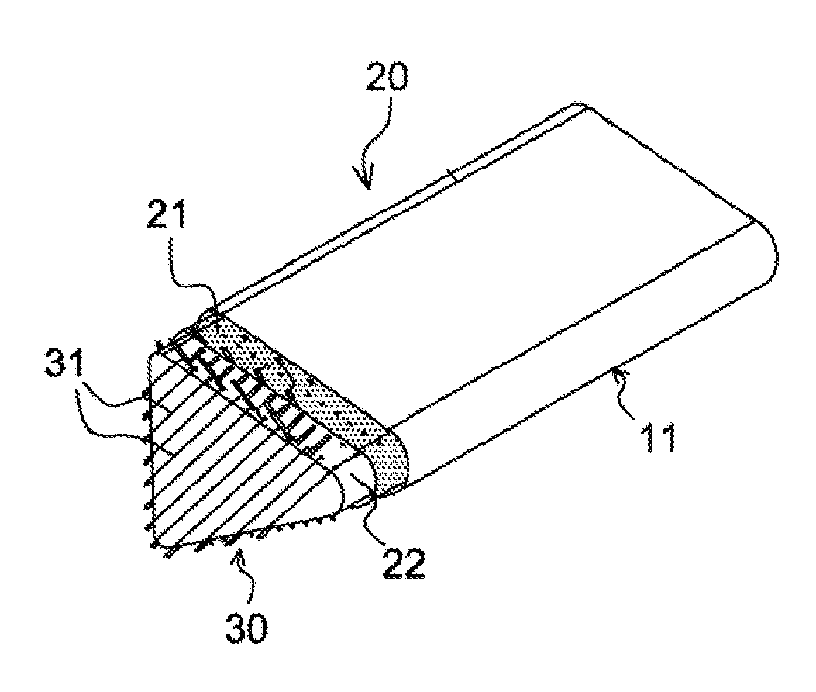
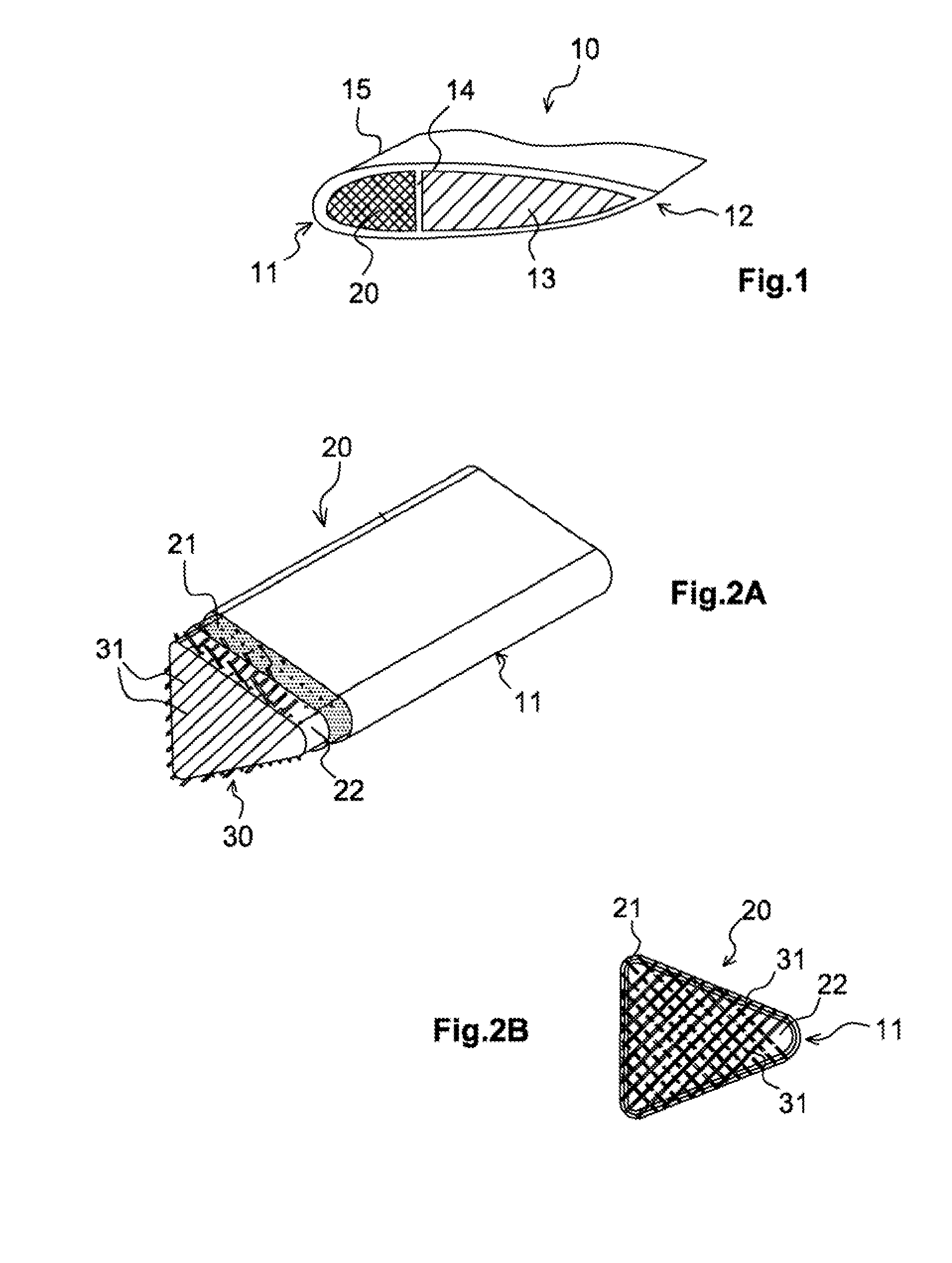
[0044]FIG. 2A depicts a partially exploded perspective view of a kinetic energy absorption device according to the invention. FIG. 2B depicts a view in cross section of this same kinetic energy absorption device. These FIGS. 2A and 2B show the kinetic energy absorption device of the invention according to the reinforcing elements.

[0045]The kinetic energy absorption device 20 of the invention comprises an outer casing 21 the role of which is to maintain the integrity of the shape of the structural element as far as possible after an impact. This outer casing 21, which will be described later on, is filled with a foam core 22 the role of which is, on the one hand, to stiffen the outer casing 21 and, on the other hand, to absorb at least some of the kinetic energy generated by the impact and to be able to become compacted so as to free up some volume as the casing deforms.

[0046]This foam core 22 comprises within it reinforcing elements 30 which allow the kinetic energy resulting from t...

second embodiment

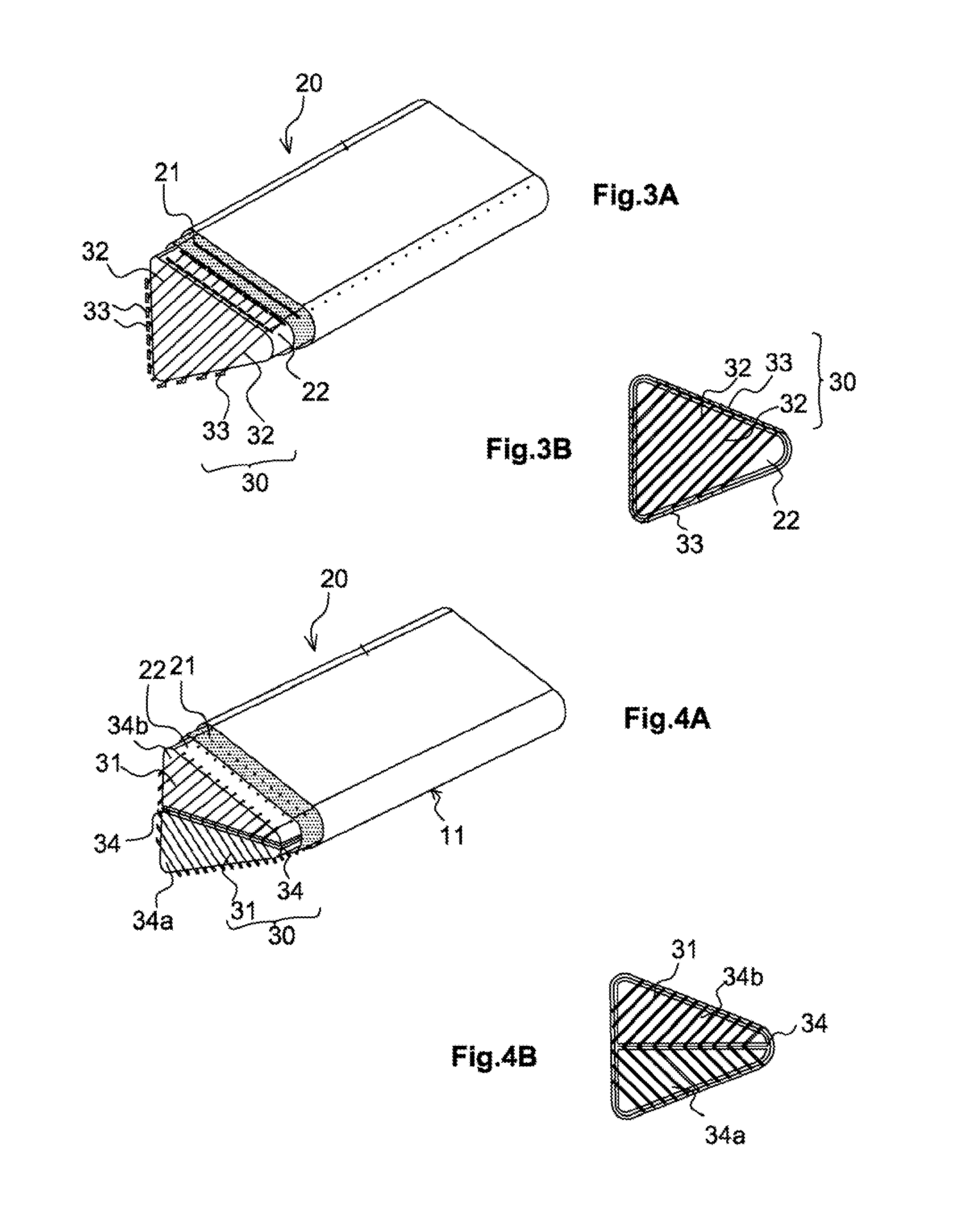
[0059]FIGS. 3A and 3B show the reinforcing elements 30 of the kinetic energy absorption device. FIG. 3A depicts a partially exploded perspective view of the kinetic energy absorption device and FIG. 3B depicts a view in section of this kinetic energy absorption device. In this embodiment, the reinforcing elements 30 are discontinuous filaments 32 each provided with an L-shaped or T-shaped head 33. In the example of FIGS. 3A and 3B, the heads are T-shaped. Whether the head 33 is L-shaped or T-shaped it is positioned at the end of the filament 32 outside the foam core 22. Each discontinuous filament 32 is therefore stitched through the foam core 22 and its end is folded over onto the outside of the foam core to form the head 33. In order to allow the overlengths of filaments 32 to be folded over onto the external wall 23 of the foam core 22 to form the head 33, a tacky binder is applied to the overlength of filament 32. Thus formed, the L-shaped or T-shaped head 33 of the discontinuou...

third embodiment

[0060]the reinforcing elements is depicted in FIGS. 6A and 6B. In this embodiment, discontinuous filaments 32 are stitched at evolving angles α. In other words, these filaments 32 are stitched so that they make an angle that is non-zero but less than or equal to 45° with respect to one another. As depicted in FIGS. 6A and 6B, the stitching is distributed from a central region of the face of the foam core opposite to the leading corner and extends as far as the edge of the foam core that forms the leading edge. In the example of FIG. 6B, the angle α between two filaments 32 is around 20°. Such a layout of filaments allows energy to be dissipated at various angles of incidence.

[0061]Whatever the type of filament, whether continuous, discontinuous, with or without a head, these filaments may be impregnated by a curable resin which allows them, after they have been stitched, to harden so that they can break upon impact.

[0062]According to another embodiment, the reinforcing elements of t...


PUM

PropertyMeasurementUnit
Densityaaaaaaaaaa
Kinetic theoryaaaaaaaaaa
Kinetic energyaaaaaaaaaa

Abstract

A device for absorbing kinetic energy for an aircraft structural element undergoing a dynamic impact. The device includes an outer enclosure made from a braided composite material configured to preserve its integrity after an impact, a foam core, contained in the outer enclosure and to at least partially fill the outer enclosure. The foam core is configured to at least partially absorb the kinetic energy generated by the impact. Reinforcing elements are integrated at least partially into the foam core to dissipate, combined with the form core, the kinetic energy generated by the impact. The reinforcing elements includes discontinuous threads inserted into the foam core by stitching, and each discontinuous thread includes an L- or T-shaped head, folded down outside the outer enclosure.

Description

FIELD OF THE INVENTION[0001]The invention relates to a passive energy absorbing device for an aircraft structural element such as a blade, a vane or any other element of a fan, wing structure or fuselage of an aircraft. This energy absorption device is designed to be integrated into a structural element of the aircraft so as to limit the risk of partial detachment or break up of the structural element in the event of an impact and thus reduce the vulnerability of this structural element to the threat of impact during flight of the aircraft.[0002]The invention also relates to an aircraft rotary structural element comprising such a kinetic energy absorption device.[0003]The invention finds applications in the field of aeronautics and notably in the field of rear-engined aircraft. It finds applications in particular in the field of the manufacture of turboprop engines and helicopter rotors and also in the field of the manufacture of composite vanes. The invention may also find applicat...

Claims


Application Information

Patent Timeline
IPC IPC(8): B64C7/00
CPCB64C7/00B64C1/062B64C3/20B64C11/26F01D21/045B64C11/205B64C2001/0072Y02T50/40Y02T50/60B64D45/00B64C3/28B64C11/20B64C27/46B32B7/08B32B5/24B32B5/22
Inventor PETIOT, CAROLINEBERMUDEZ, MICHELMESNAGE, DIDIER
Owner EURON AERONAUTIC DEFENCE & SPACE
Why Eureka
Try Eureka