Asset Condition Monitoring

a technology for condition monitoring and assets, applied in the field of asset monitoring, can solve the problems of inability to detect any new abnormal behaviour that is present in the system, less able to accommodate any short-lived, transient behaviour, and not always availabl

Inactive Publication Date: 2015-12-03
ROLLS ROYCE PLC
View PDF0 Cites 27 Cited by
  • Summary
  • Abstract
  • Description
  • Claims
  • Application Information

AI Technical Summary

Benefits of technology

[0029]The diagnostic system may further comprise a system / diagnosis model modification module or tool. The modification tool may be programmable or updatable automatically and / or by a human operator of the machine. The modification tool may be updated using in-service data. The modification tool may be used to update the anomaly detector and / or the fault classifier. This is beneficial as each machine will have different characteristics and signatures, and so the modification tool allows the fault diagnostic framework of the invention to be utilised for machines with different parameters and varying tolerances.

Problems solved by technology

The failure of a rotating electrical machine is often preceded by a period in which the machine can still operate to perform the desired function, for example rotating at the intended operational speed, but during which the machine operates with different internal electrical characteristics to those present in normal operation, for example by drawing a larger amount of current in one of the machine windings.
However such a conventional method is only capable of detecting specific known types of abnormalities, and therefore is unable to detect any new abnormal behaviour that is present in the system.
This has the disadvantage of being less able to accommodate any short-lived, transient behaviour that is present in the signal.
A further disadvantage of the methods discussed above includes the assumption that there is an underlying state that can be detected more accurately through several observations.
This requires prior knowledge of characteristics of the incipient fault state, which is not always available.
Furthermore, there is a common assumption of system non-stationarity, which is not true since system characteristics change with time in-service.
Conventional diagnostic systems are not generally robust to such variations.
With such an assumption in place, there is a risk of the misclassification of unknown faults.

Method used


Image

  • Asset Condition Monitoring
  • Asset Condition Monitoring
  • Asset Condition Monitoring

Examples


Embodiment Construction

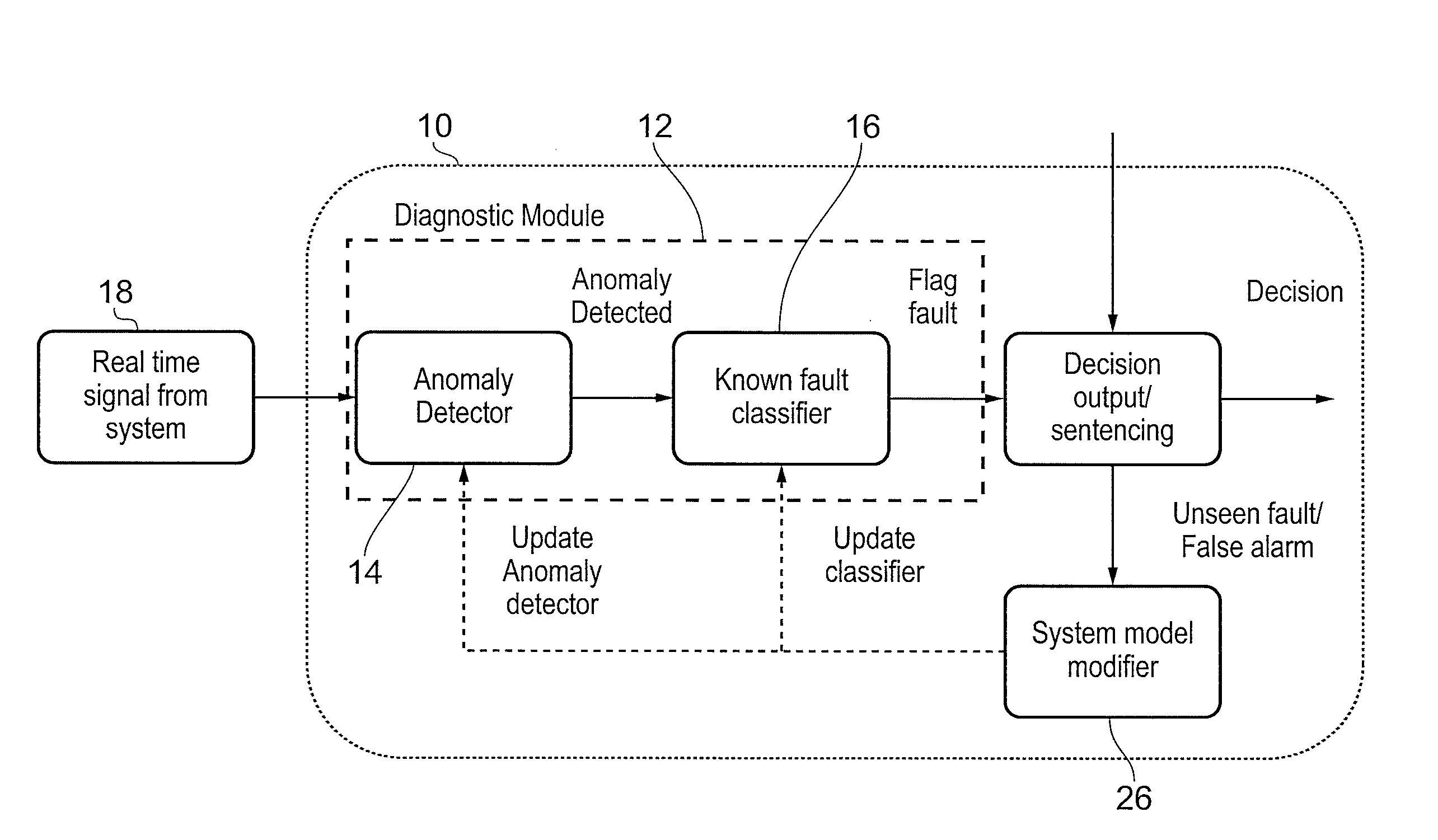
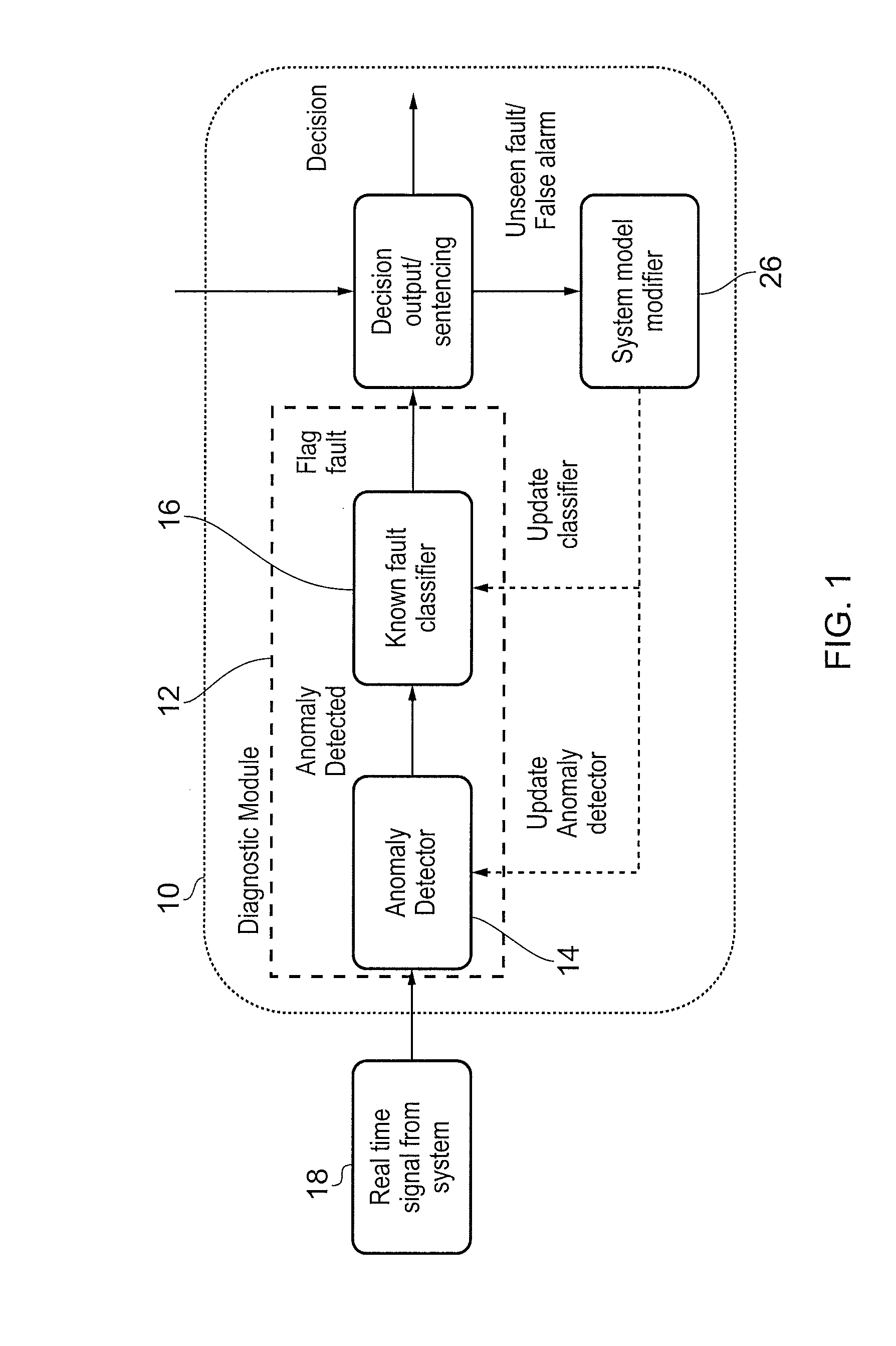
[0038]The present invention derives in general from the realisation by the inventors that the manner in which faults / anomalies are identified by equipment health monitoring systems can be tailored to identify previously unknown or unrecognised faults, in a way which allows those faults to be accommodated in future machine health diagnoses.

[0039]An asset as referred to herein typically refers to a machine or a number of machines that are inter-reliant for correct operation thereof. The following description focuses on electrical machines, e.g. as used within a gas turbine engine, in particular but can be generalised to other kinds of machine, including the larger gas turbine engine or other complex systems, for which similar considerations apply. The invention is particularly suited to complex, high value or safety-critical machines, which have multiple potential failure modes and, for which, the possible failure modes could interact. The invention may be beneficial where the cost of...


PUM


Abstract

Invention concerns a machine fault diagnostic system. Sensors are provided for sensing an operational parameter of the machine over time in use and outputting corresponding sensor signals. A machine operation diagnosis tool is arranged to receive the sensor signals and has a data store for operational parameter data indicative of a normal mode of machine operation and operational parameter data indicative of one or more known machine faults. The diagnosis tool has one or more processor arranged to compare the received sensor signals with the operational parameter data in the data store in order to determine a match with either the normal mode of operation or the one or more known machine fault, and wherein the processor sentences an unknown fault in the event that said match is not established. The system may record unknown faults and update the diagnosis tool as unknown faults become recognizable faults.

Description

BACKGROUND OF THE INVENTION[0001]The present invention relates to asset monitoring, and in particular to machine operation health monitoring and / or management systems, typically allowing machine fault diagnostics.[0002]The failure of a rotating electrical machine is often preceded by a period in which the machine can still operate to perform the desired function, for example rotating at the intended operational speed, but during which the machine operates with different internal electrical characteristics to those present in normal operation, for example by drawing a larger amount of current in one of the machine windings. Hence, the electrical operating conditions of such machines are often captured using a monitoring system, thereby allowing anomalies to be detected such that a failure of the machine may be pre-empted.[0003]Many methods exist for detecting anomalies in operating conditions, and one such method is to detect the changes in the monitoring signals that signify a speci...

Claims


Application Information

Patent Timeline
Patent Type & Authority Applications(United States)
IPC IPC(8): G01M99/00
CPCG01M99/008G05B23/0221
Inventor DUTTA, PARTHACHI-KEONG, GOHNADARAJAN, SIVAKUMARYANG, FENGXU, ZHAOKUO, SHYH-HAO
Owner ROLLS ROYCE PLC
Why Eureka
Try Eureka