Method for monitoring urea quality of an scr system

a technology of scr system and urea quality, which is applied in the direction of positive displacement liquid engine, indirect flow property measurement, instruments, etc., can solve the problems of increasing the overall cost of the scr system, requiring significant packaging space, and difficult to place and use such a urea quality sensor in existing scr systems, etc., to achieve enhanced accuracy and simplicity

Inactive Publication Date: 2015-12-10
PLASTIC OMNIUM ADVANCED INNOVATION & RES SA
View PDF8 Cites 9 Cited by
  • Summary
  • Abstract
  • Description
  • Claims
  • Application Information

AI Technical Summary

Benefits of technology

[0013]It is, therefore, one aspect of the present invention to provide for a method f

Problems solved by technology

One shortcoming of these known urea quality sensors is that they generally require significant amount of packaging space.
Moreover, it is difficult to place and use such a urea quality sensor in existing SCR sys

Method used


Image

  • Method for monitoring urea quality of an scr system
  • Method for monitoring urea quality of an scr system
  • Method for monitoring urea quality of an scr system

Examples


Embodiment Construction

[0049]The same reference numerals are used to indicate the same elements (or functionally-similar elements) throughout the separate FIGS. 1 to 5.

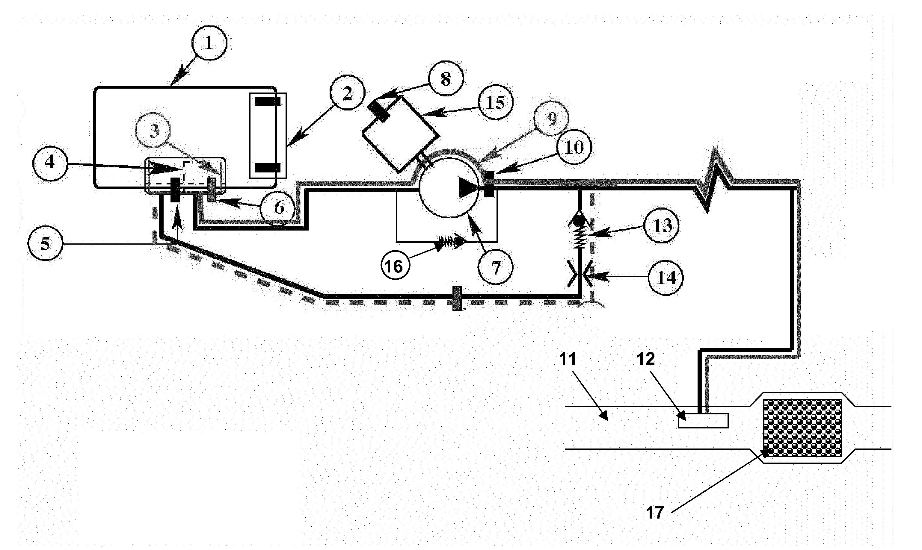
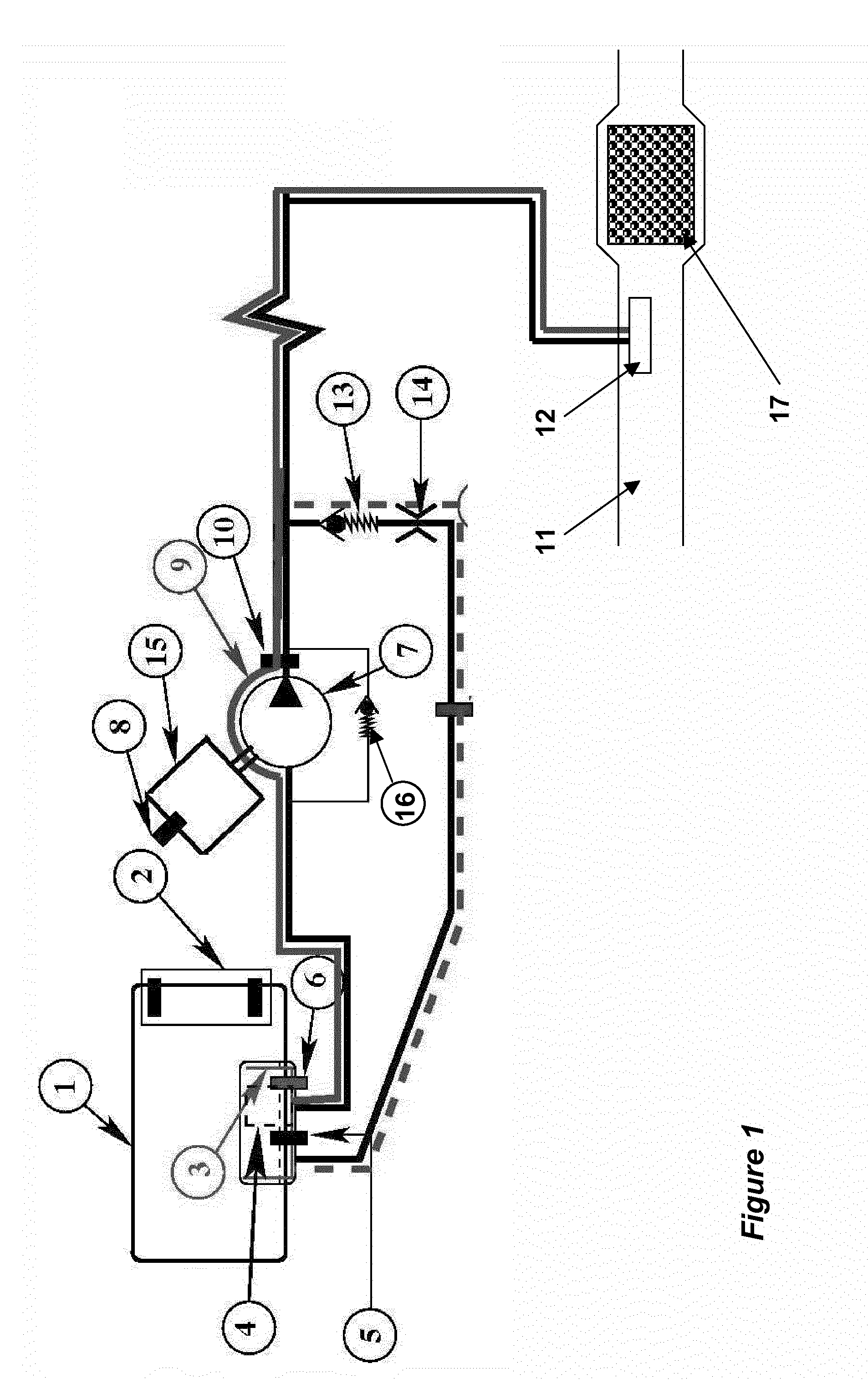
[0050]FIG. 1 illustrates a particular embodiment of a SCR system to which the present invention may be applied

[0051]The SCR system comprises a urea tank (1) containing a urea solution. The urea tank (1) is equipped with the following components:[0052]a gauge (2) (i.e. level sensor);[0053]a heating element (3);[0054]a filter (4);[0055]a temperature sensor (5); and[0056]a current sensor for the heating element (6).

[0057]The urea solution is conveyed by the action of a pump (7) towards an injector (12) located in a line (11) for discharging the exhaust gases of the engine of the vehicle, upstream of a SCR catalyst (17). The pump (7) is driven by a BLDC motor (15) and which is controlled by a controller (non illustrated). The controller can receive a signal (relative to the outlet pressure of the pump) measured by a pressure sensor (10) and a s...


PUM


Abstract

A method for monitoring urea concentration and quality in a urea solution stored in a tank of an SCR system. The system comprising a pump driven by a motor and the pressure of which is controlled by a controller. The method comprises the steps of:—measuring a parameter value characteristic of the energy transmitted by the motor to the pump;—determining a urea concentration value based upon the parameter value characteristic of the energy transmitted by the motor to the pump.

Description

TECHNICAL FIELD[0001]The present invention relates to a method for determining fluid quality. In particular it relates to a method for sensing urea concentration / quality in a urea solution stored in a tank of a SCR system.BACKGROUND OF THE INVENTION[0002]Legislation on vehicle and heavy goods vehicle emissions stipulates, amongst other things, a reduction in the release of nitrogen oxides NO into the atmosphere. One known way to achieve this objective is to use the SCR (Selective Catalytic Reduction) process which enables the reduction of nitrogen oxides by injection of a reducing agent, generally ammonia, into the exhaust line.[0003]This ammonia may derive from the pyrolytic decomposition of an ammonia precursor solution, whose concentration may be the eutectic concentration. Such an ammonia precursor is generally a urea solution.[0004]With the SCR process, the high levels of NOx produced in the engine during combustion at optimized efficiency are treated in a catalyst after exitin...

Claims


Application Information

Patent Timeline
IPC IPC(8): F01N11/00G01N11/00F01N3/20
CPCF01N11/00F01N3/208G01N11/00F01N2550/05F01N2610/02F01N2610/144Y10T137/85986F01N2900/0412F01N2900/1822F01N2900/1818F01N2610/1406Y10T137/0335F01N2610/148F01N3/2066G01N2011/0053F01N2900/1808G01N2011/006Y02T10/12
Inventor THOMPSON, JAMES EDWARDHABUMUREMYI, JEAN-CLAUDEBUTLER, JOSHLEONARD, STEPHANEJANNOT, FREDERIC
Owner PLASTIC OMNIUM ADVANCED INNOVATION & RES SA
Why Eureka
Try Eureka