Optical element with high scratch resistance

Inactive Publication Date: 2015-12-10
SCHOTT AG
View PDF6 Cites 18 Cited by
  • Summary
  • Abstract
  • Description
  • Claims
  • Application Information

AI Technical Summary

Benefits of technology

[0014]It is believed that the organofluoro layer, although it is not itself hard, reduces interaction with the surface. In particular, it also happens here that the uppermost oxide layer of the anti-reflection coating has a hardness that is less than that of the nitride layer following thereon based on the alternating sequence of layers. In this case, an effect is based on a reduction in the friction coefficient of the surface due to the organofluoro molecules.
[0015]The organofluoro layer prevents the formation of chemical bonds between the surface and an abrasive medium, as is produced during an effective abrasion. Thus, glass is readily polished with cerium oxide, since the latter compound forms covalent bonds with glass and thus clearly

Problems solved by technology

This single-molecule layer is thus not active optically or is just

Method used


Image

  • Optical element with high scratch resistance
  • Optical element with high scratch resistance
  • Optical element with high scratch resistance

Examples


Example

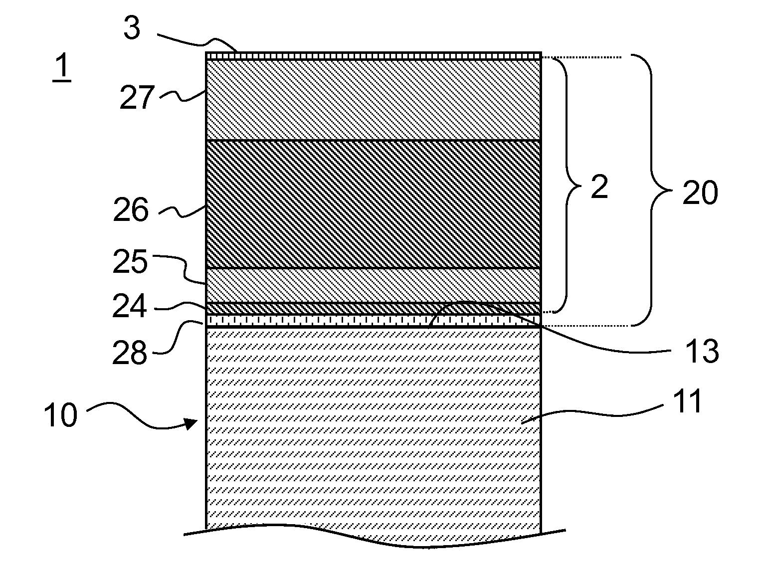
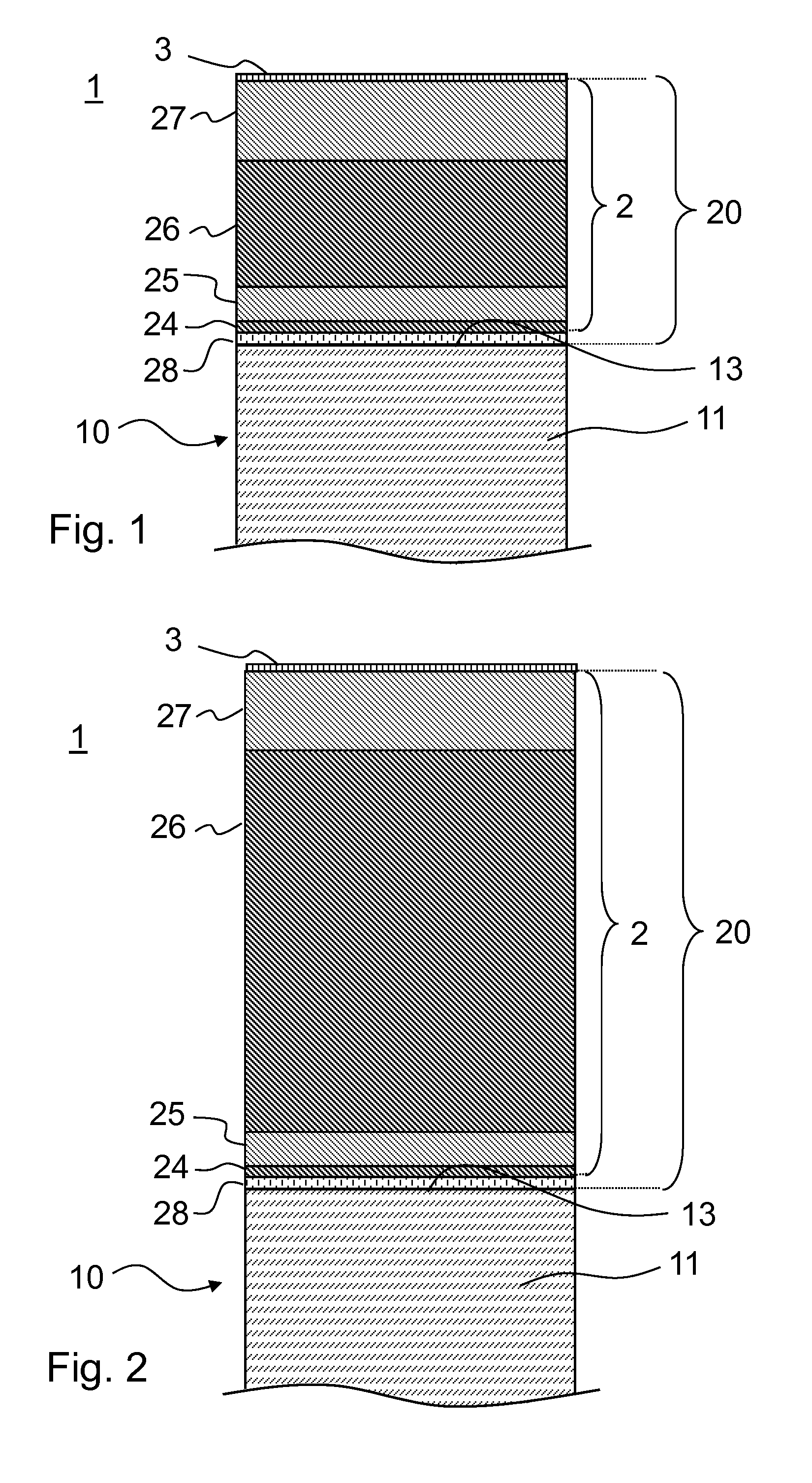
[0028]FIG. 1 and FIG. 2 show examples of optical elements 1 according to the invention with high scratch resistance, having a transparent substrate 10 in the visible spectral region, and a multilayer anti-reflection coating 2 deposited on the substrate 10. Layers 25, 27 of the anti-reflection coating 2 having a first refractive index alternate with layers 24, 26 having a second, higher refractive index in comparison to the first refractive index.

[0029]A layer 3 of chain-form organofluoro molecules is disposed on the uppermost layer 27 of the anti-reflection coating, wherein the molecules are bonded at their ends to the surface of the uppermost layer 27 of the anti-reflection coating 2.

[0030]The organofluoro molecules preferably contain perfluorinated carbon chains, in which all hydrogen atoms, in particular, can also be replaced by fluorine atoms. In addition, the organofluoro molecules are preferably individually covalent at the surface of the optical element 1. The individual mole...


PUM

PropertyMeasurementUnit
Fractionaaaaaaaaaa
Thicknessaaaaaaaaaa
Thicknessaaaaaaaaaa

Abstract

An optical element is provided that includes a substrate that is transparent in the visible spectral region and a multilayer anti-reflection coating on the substrate. The coating has alternating layers of layers having a first refractive index and of layers having a second, higher refractive index. The layers having the higher refractive index contain nitride or oxynitride and the layers having the first refractive index contain oxide of silicon and of at least one other element. The molar fraction of silicon in the layers having the first refractive index is predominant when compared to the molar fraction(s) of the other element or elements. The uppermost layer of the coating is a layer having the first refractive index. A layer of chain-form organofluoro molecules is disposed on the coating, wherein the molecules are bonded at the ends to the surface of the optical element.

Description

CROSS REFERENCE TO RELATED APPLICATIONS[0001]This application claims benefit under 35 U.S.C. §119(a) of German Patent Application No. 10 2014 108 058.0 filed Jun. 6, 2014, the entire contents of which are incorporated herein by reference.BACKGROUND[0002]1. Field of the Disclosure[0003]In general, the invention relates to optical elements, such as viewing panels or cover glasses for optical displays, for example, of mobile phones or watches, or for optical systems, such as, for example, objectives or optical measuring instruments. In particular, the invention relates to measures for improving the stability of the surface relative to scratching.[0004]2. Description of Related Art[0005]In order to protect surfaces of optical elements against scratching, it is known to provide the surface with a hard coating. Thus, a hard anti-reflection coating is known from EP 2492251 A1.[0006]However, it has been determined by the present disclosure that there is a continuing need for coatings with i...

Claims


Application Information

Patent Timeline
IPC IPC(8): G02B1/11C23C14/00C23C14/46G02B1/14
CPCG02B1/11C23C14/46C23C14/0036G02B1/14C03C17/42G02B1/111C23C14/3414G02B1/115B29D11/00865
Inventor APITZ, DIRKWALTHER, MARTENHENN, CHRISTIAN
Owner SCHOTT AG
Why Eureka
Try Eureka