
Nuclear reactor coolant pump with high density composite flywheel

a composite flywheel and nuclear reactor technology, applied in the field of nuclear reactor arts, nuclear power arts, reactor coolant pump arts, can solve the problems of tungsten in the nuclear reactor environment, adversely affecting the normal operation function of the nuclear reactor, and modifying these components to increase the moment of inertia, so as to reduce the fluid resistance of the rotating assembly in water.

Inactive Publication Date: 2015-12-10
BWXT MPOWER INC
View PDF4 Cites 6 Cited by
  • Summary
  • Abstract
  • Description
  • Claims
  • Application Information

AI Technical Summary

Benefits of technology

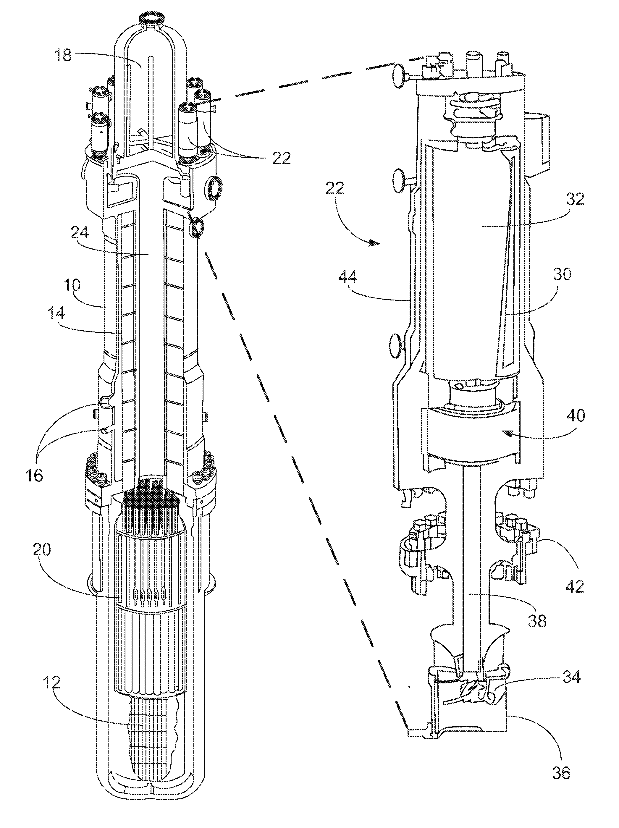
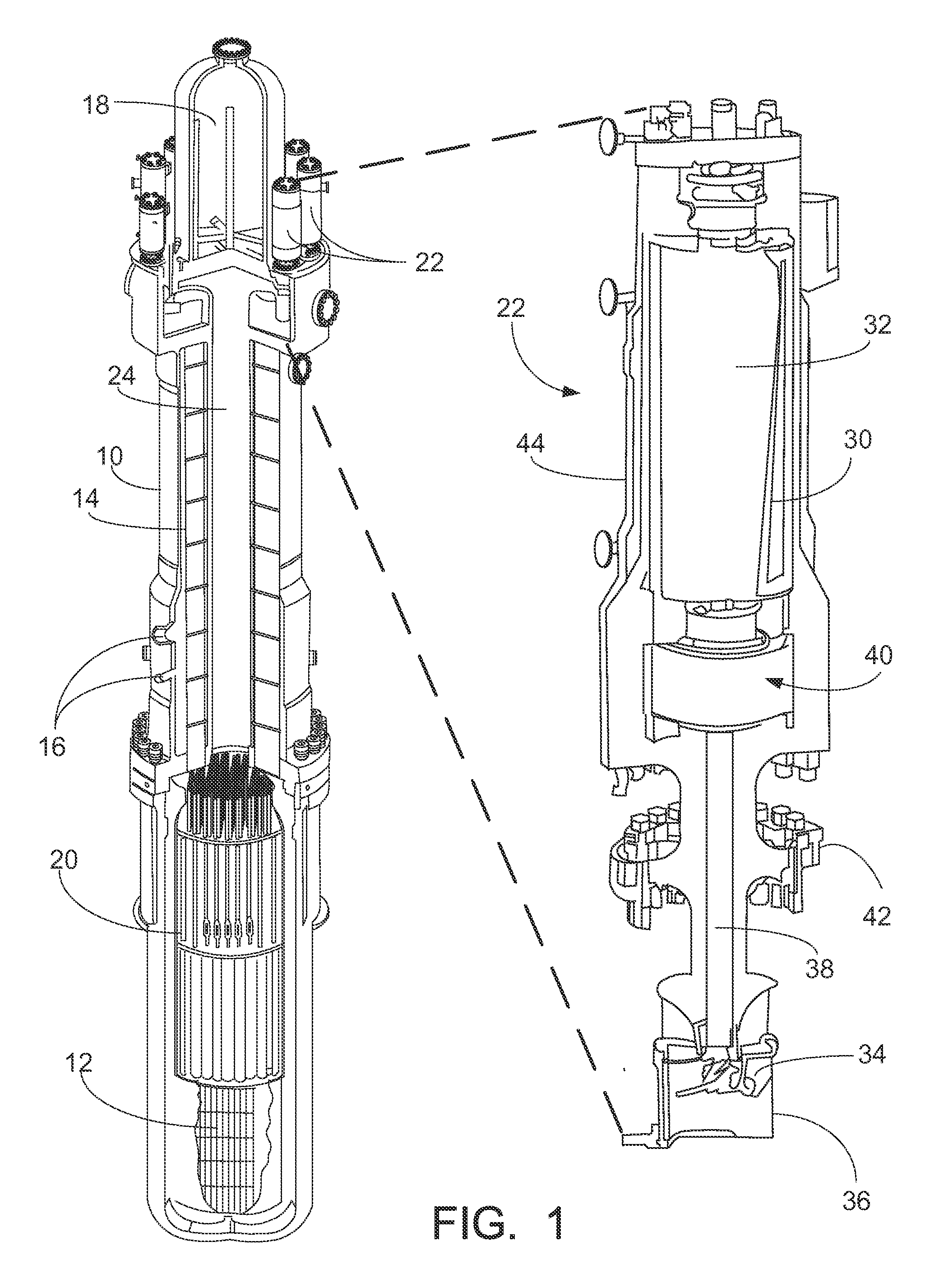
This patent describes a reactor coolant pump with a stator and rotating assembly including a rotor, impeller, and flywheel. The flywheel is made of a first material and has cylindrical openings filled with a second material that is denser than the first material. The flywheel is designed to reduce fluid resistance in water. The reactor coolant pump is operable to rotate the rotoring assembly in response to an electrical energy. The technical effect of this design is to improve the pump's efficiency and performance. The reactor coolant pump may be used in a nuclear reactor with a reactor pressure vessel and fissile -235U disposed therein.

Problems solved by technology

This presents a problem because the RCP shut off terminates coolant circulation at the beginning of SCRAM, when the residual decay heat output of the reactor core is highest.
Modifying these components to increase the moment of inertia can be problematic since such modification can adversely impact their normal operational function.
However, tungsten can be problematic in the nuclear reactor environment, and also exhibits differential thermal expansion as compared with surrounding steel components.

Method used


Image

  • Nuclear reactor coolant pump with high density composite flywheel
  • Nuclear reactor coolant pump with high density composite flywheel
  • Nuclear reactor coolant pump with high density composite flywheel

Examples


Embodiment Construction

[0019]Disclosed herein are high density composite flywheels that provide the advantages of increased density as compared with a steel flywheel while maintaining ease of manufacturing and efficient use of the high density (e.g. tungsten) material. The disclosed flywheels are based on several observations.

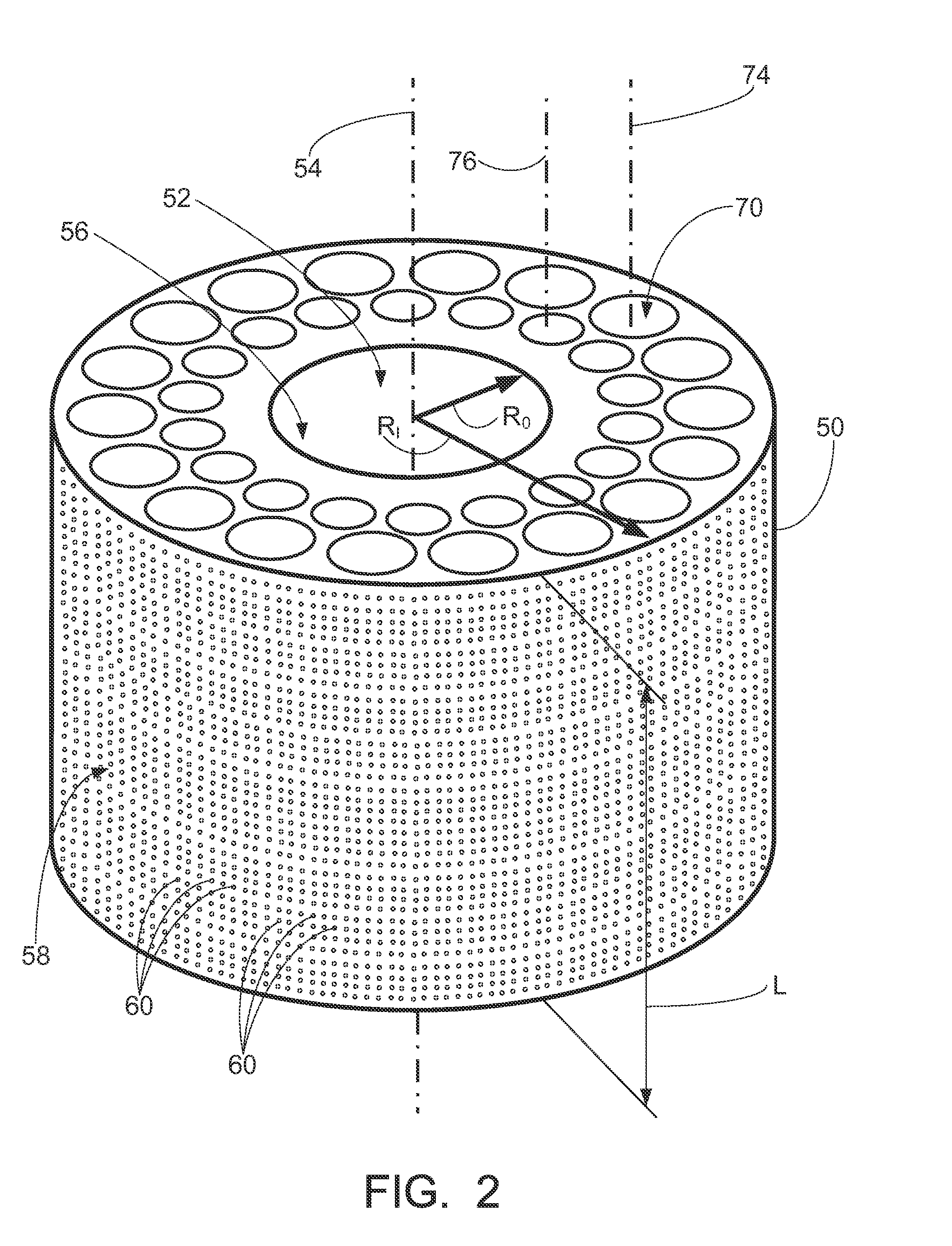
[0020]The moment of inertia I of a rotating body (e.g. flywheel) can be calculated as I=∫V ρ(r)r2 where r is a radius vector to a point in the body from the axis of rotation, and ρ(r) is the mass density at that point. For a cylindrical flywheel that includes a given mass of high density material (e.g. tungsten), increased moment of inertia I is seen to be obtained by preferentially locating the high-density material outboard, that is, relatively nearer to the outer circumference of the cylindrical flywheel, corresponding to large radius (r) values. The contribution to the integral I goes with the square of the radius (r2), making this a super-linear effect.

[0021]It is also recognize...


PUM

PropertyMeasurementUnit
axis of rotationaaaaaaaaaa
fluid resistanceaaaaaaaaaa
surface textureaaaaaaaaaa

Abstract

A nuclear reactor coolant pump (RCP) comprises a stator and a rotating assembly including a rotor, an impeller, and a flywheel configured to rotate about an axis of rotation in response to the stator being electrically energized. The flywheel comprises a first material (such as stainless steel) and has a plurality of mutually parallel tubular openings filled with a second material that is denser than the first material (such as tungsten or tungsten alloy). In some embodiments the mutually parallel tubular openings are cylindrical openings, and are filled with the second material comprising cylindrical rods. In a nuclear reactor including a reactor pressure vessel and a nuclear reactor core comprising fissile 235U disposed in the reactor pressure vessel, the RCP is suitably disposed on or in the reactor pressure vessel with the impeller of the RCP arranged to engage coolant water disposed in the reactor pressure vessel.

Description

[0001]This application was conceived in the course of work supported by the Department of Energy Cooperative Agreement No. DE-NE0000583. The Department of Energy may have certain rights in this application.BACKGROUND[0002]The following pertains to the nuclear reactor arts, nuclear power arts, reactor coolant pump arts, and related arts.[0003]A typical nuclear reactor comprises a radioactive reactor core disposed in coolant in a reactor pressure vessel. For example, a light water reactor employs purified water as the coolant, and the reactor core typically comprises a uranium composition such as uranium oxide (UO2) enriched in the fissile 235U isotope. In operation, the nuclear reactor core supports a nuclear chain reaction that heats the coolant, and the coolant is brought into thermal communication with secondary coolant (typically water) in a steam generator to convert the secondary coolant to working steam to drive a turbine in the case of an electric power plant, or to perform s...

Claims


Application Information

Patent Timeline
Patent Type & Authority Applications(United States)
IPC IPC(8): G21C15/18B23K31/02G21C21/02
CPCG21C15/182Y10T29/49828B23K31/02G21C21/02F04D7/08G21C1/322G21C15/243F16F15/30Y02E70/30Y02E30/30
Inventor ALES, MATTHEW W.GODDEN, MARK C.
Owner BWXT MPOWER INC
Learn More