Laser light source device

a laser light source and laser light source technology, applied in semiconductor devices, light sources, lighting and heating apparatus, etc., can solve the problems of reduced efficiency, large light exit angle and efficiency of leds, short lifespan,

Active Publication Date: 2015-12-10
LG ELECTRONICS INC
View PDF1 Cites 21 Cited by
  • Summary
  • Abstract
  • Description
  • Claims
  • Application Information

AI Technical Summary

Benefits of technology

[0032]At least one embodiment of the present invention may provide a high-power and s...

Problems solved by technology

However, LEDs have a large light exit angle and efficiency which is reduced at high current and are restricted as a light source of a high power illumination device or a laser light source device emitting light toward a s...

Method used


Image

  • Laser light source device
  • Laser light source device
  • Laser light source device

Examples


Embodiment Construction

[0047]Hereinafter, a laser light source device in accordance with the present invention will be described in detail with reference to the accompanying drawings.

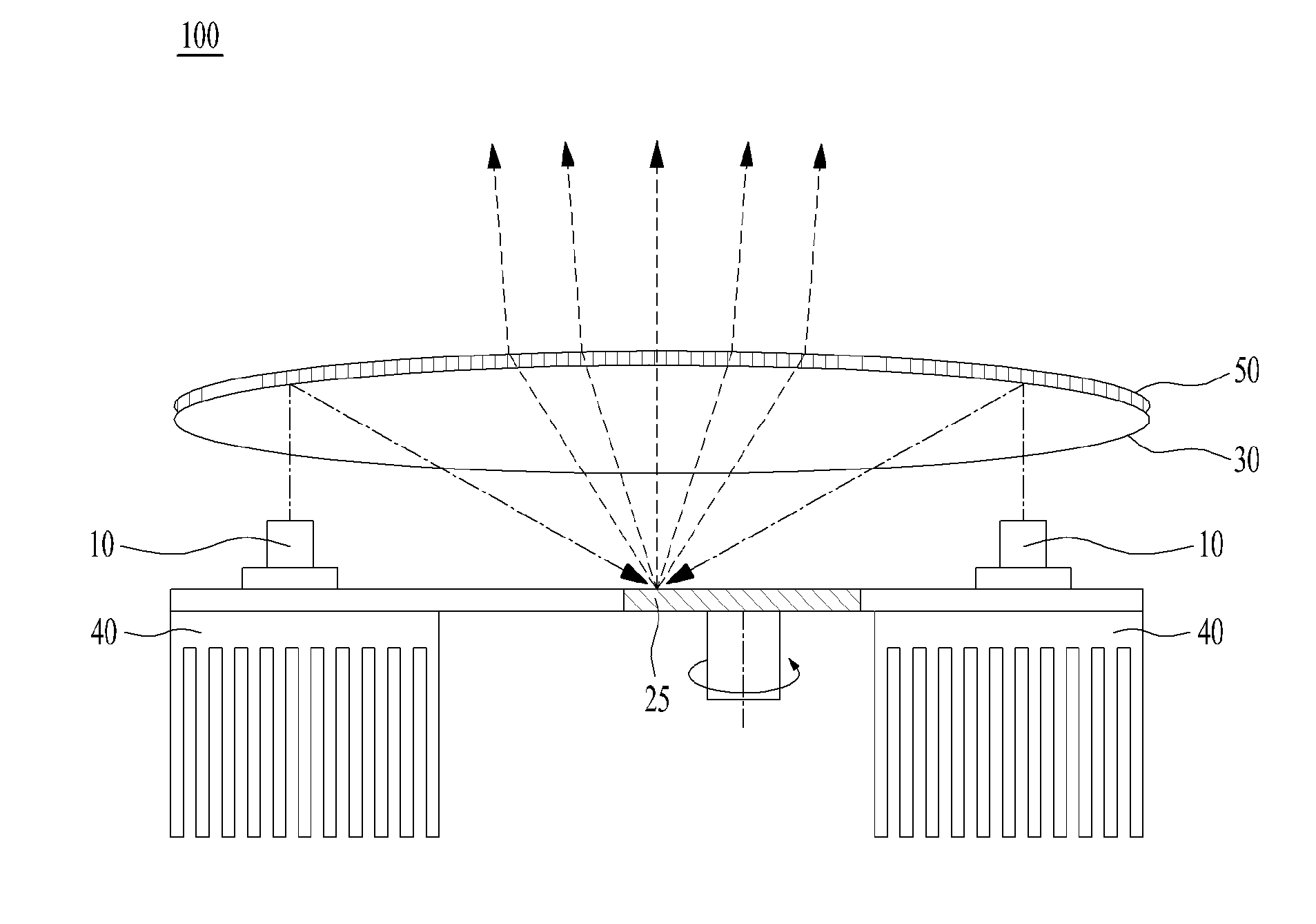
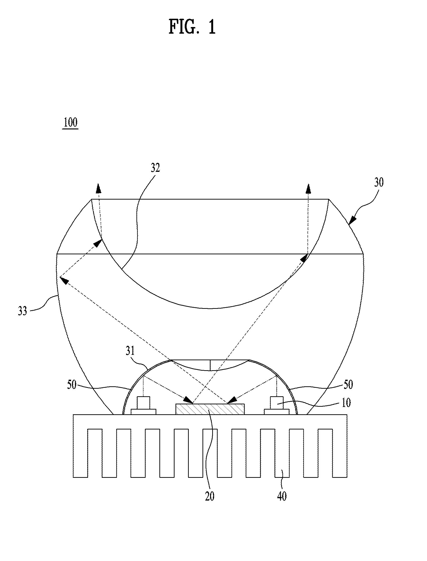
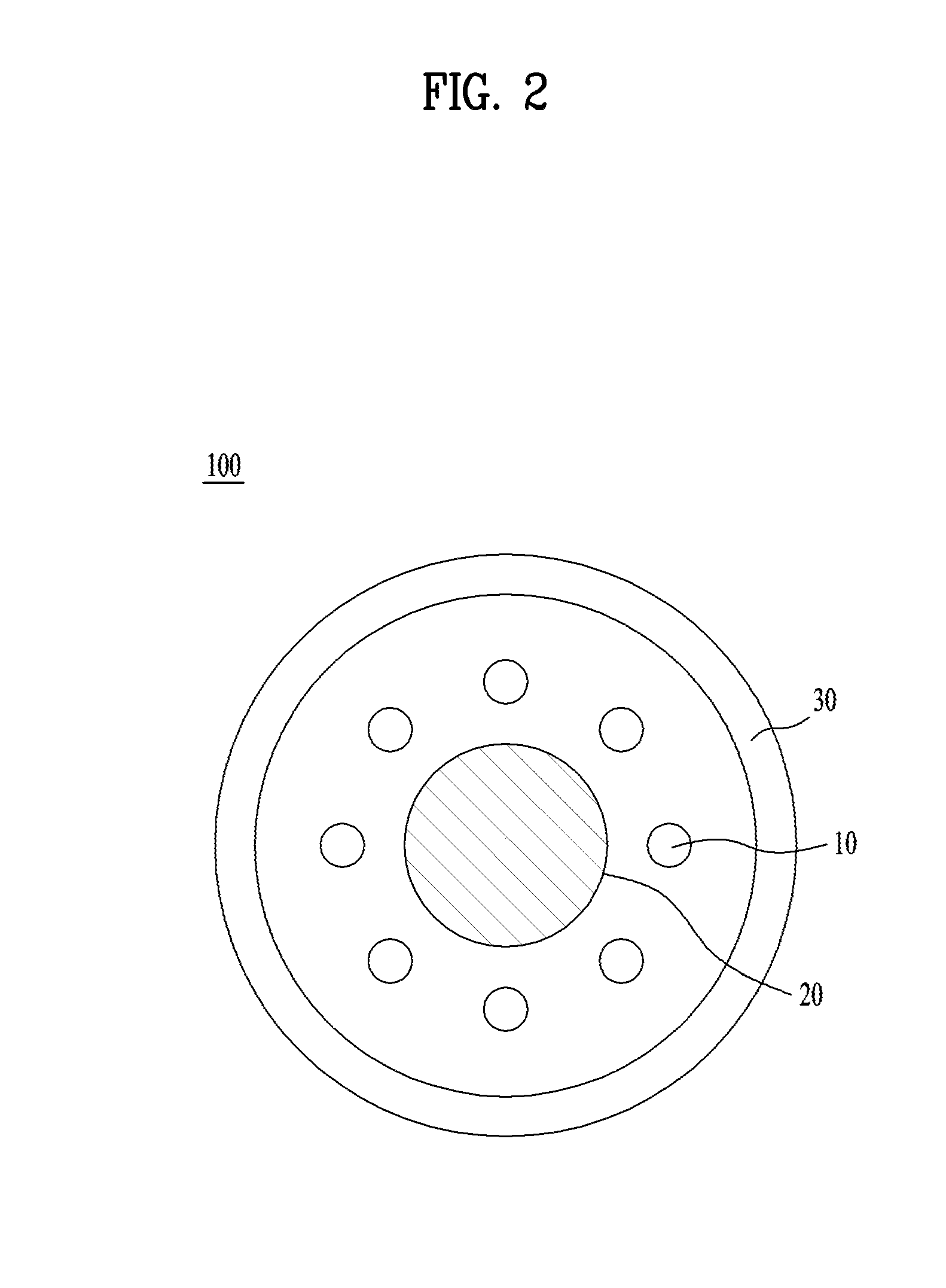
[0048]FIG. 1 is a cross-sectional view illustrating a laser light source device 100 in accordance with one embodiment of the present invention, and FIG. 2 is a plan view of the laser light source device 100 in accordance with the embodiment of FIG. 1. With reference to FIGS. 1 and 2, laser diodes 10, a wavelength conversion plate 20, a reflection unit 50, a projection unit 30, and a radiation fin 40 are illustrated.

[0049]The laser diode 10 is a semiconductor element emitting light according to an electrical signal. The laser diode 10 emits light of a narrow wavelength band, as compared to a light emitting diode, and the emitted light has straightness.

[0050]Since the laser diode 10 amplifies light and then emits the amplified light, the laser diode 10 has a high power, as compared to a light emitting diode, has a small size, a...


PUM


Abstract

A laser diode includes a laser diode emitting light due to an electrical signal; a wavelength conversion plate for shifting the wavelength of the light emitted from the laser diode; a reflecting part for reflecting the light emitted from the laser diode towards the wavelength conversion plate; and a projecting part for emitting, in the forward direction, the light shifted by the wavelength conversion plate. The laser diode can provide a high-power but small-sized laser light source device, and a narrow emission angle can be achieved using the laser diode.

Description

BACKGROUND OF THE INVENTION[0001]1. Technical Field[0002]The present invention relates to a high-power and small-sized laser light source device emitting light having straightness using blue or ultraviolet laser diodes.[0003]2. Background Art[0004]Light emitting diodes (LEDs) have been developed as conventional leading light sources and are being used as main light sources and continuously developed now. However, LEDs have a large light exit angle and efficiency which is reduced at high current and are restricted as a light source of a high power illumination device or a laser light source device emitting light toward a small area.[0005]Owing to such restriction, instead of LEDs, a high-intensity discharge (HID) lamp, a metal halide lamp, an ultra high performance (UHP) lamp and the like are used as high power light sources. However, since the laser light source device has problems, such as a short lifespan, environmental regulation, low efficiency and the like, a new light source s...

Claims


Application Information

Patent Timeline
IPC IPC(8): H01S5/022F21V9/16F21V7/00H01S5/323
CPCH01S5/02296H01S5/32341F21Y2101/025F21V7/0066F21V9/16H01S5/02208F21V5/04F21V7/0008H01S5/02469F21Y2101/00F21K9/64F21Y2115/30F21V9/30F21V9/06F21V13/14H01S5/02257H01S5/0087H01S5/02255H01S5/06H01S5/02
Inventor JEOUNG, BYUNGWOOBAE, YONGWOOYEO, SANGOKLEE, SEUNGGYU
Owner LG ELECTRONICS INC
Why Eureka
Try Eureka