Mosfet driver with pulse timing pattern fault detection and adaptive safe operating area mode of operation

a technology of mosfet and driver, applied in the direction of pulse technique, process and machine control, instruments, etc., can solve the problems of simultaneous application of high voltage and current to the switch, oscillatory voltage spikes may be produced in the mosfet power transistor, and the effect of avoiding the production of oscillatory voltage spikes

Active Publication Date: 2015-12-10
POWER INTEGRATIONS INC
View PDF0 Cites 25 Cited by
  • Summary
  • Abstract
  • Description
  • Claims
  • Application Information

AI Technical Summary

Problems solved by technology

However, limitations and characteristics of real devices may make it impractical (if not impossible) to protect the switch under all conditions.
For example, the presence of parasitic inductance and capacitance in a Flyback converter may result in the simultaneous application of high voltage and current to the switch during switching events.
In particular, an oscillatory voltage spike may be produced in a MOSFET power transistor during turn-off due to energy storage in the leakage inductance of the transformer.
Additionally, the parasitic / stray capacitance may generate a considerable current spike during turn-on as the voltage of the transformer primary winding changes (e.g., from a positive input voltage Vin to a negative reflected output voltage −Vor).
While the VI locus of the Power MOSFET can be effectively maintained within the SOA during normal operation, the use of the blanking time may hinder or prevent this under certain transient and fault conditions (e.g., at startup or during an output short circuit).
As a result, the turn-on and the turn-off VI locus of the converter may exceed the SOA envelope of the Power MOSFET and cause a destructive breakdown of the device.
In the event that the output voltage drops low (e.g., during a partial or complete short circuit at the output, an overload condition, or start-up), traditional techniques that respond to excess current in the switch may be unable to prevent the current from exceeding desirable levels in a switching period.

Method used


Image

  • Mosfet driver with pulse timing pattern fault detection and adaptive safe operating area mode of operation
  • Mosfet driver with pulse timing pattern fault detection and adaptive safe operating area mode of operation
  • Mosfet driver with pulse timing pattern fault detection and adaptive safe operating area mode of operation

Examples


Embodiment Construction

[0026]In the following description, numerous specific details are set forth in order to provide a thorough understanding. It will be apparent, however, to one having ordinary skill in the art that the specific details need not be employed.

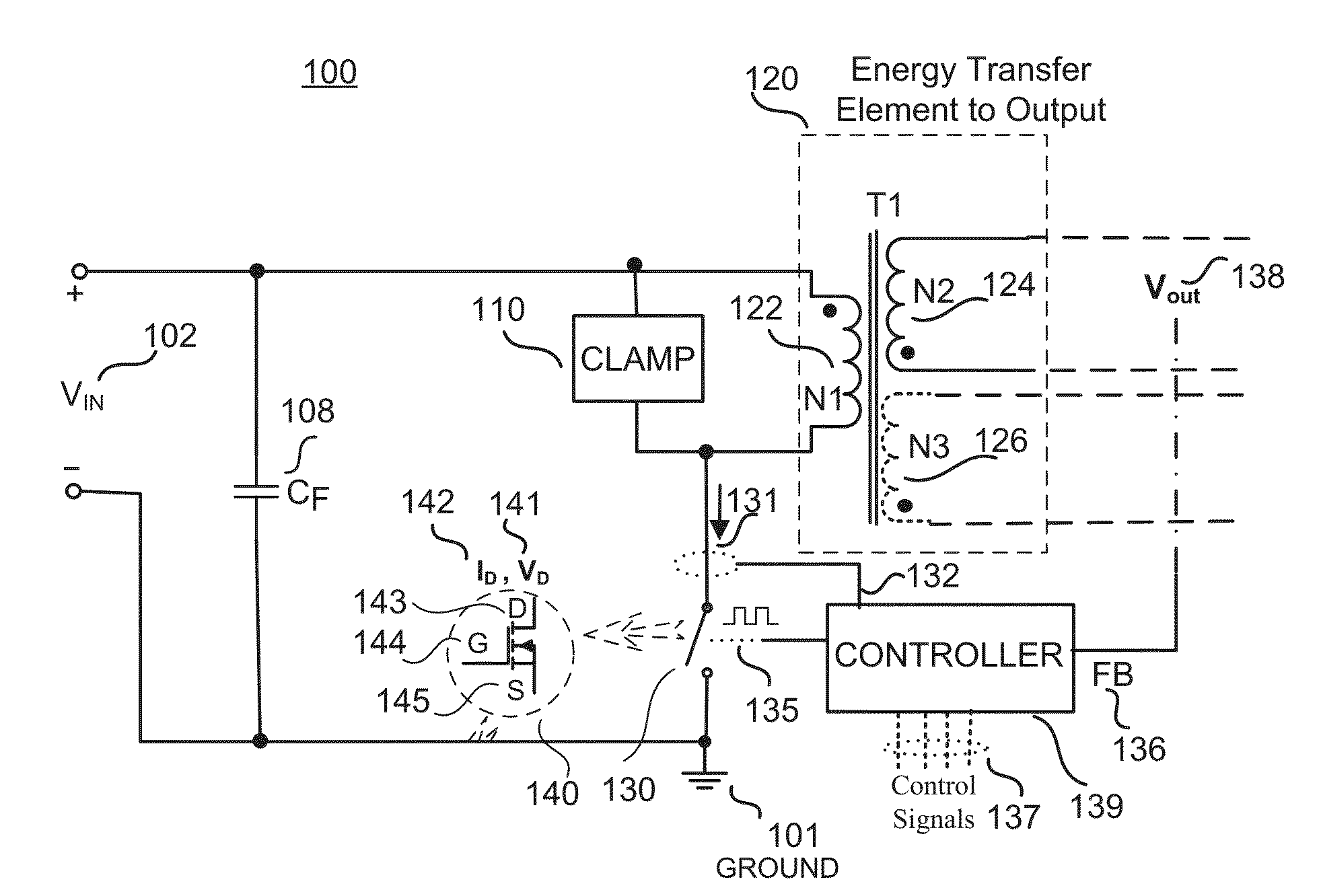
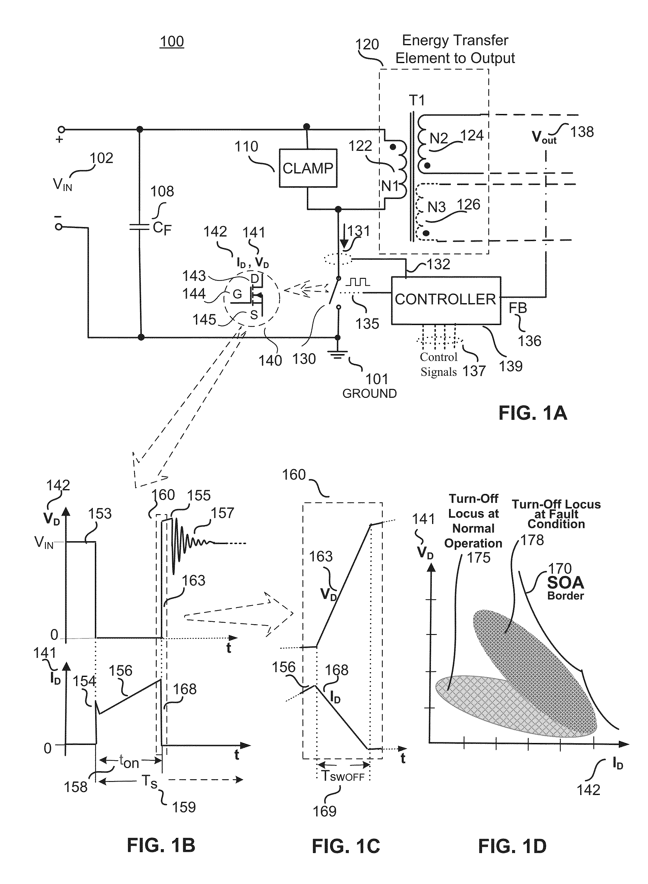
[0027]Various examples directed to an adaptive gate driver that is designed to maintain a switch mode power converter in a SOA are disclosed. In response to a detection of a fault condition, the SOA adaptive gate driver may limit the peak current in a Power MOSFET of the power converter by limiting the voltage applied to the gate of the power switch or by limiting the current injected into the gate of the power switch. The limited gate voltage or current may increase the margin between an SOA border and the turn-off locus of the drain voltage and current (VD / ID) to ensure safe operation of the power converter during the fault condition. This may allow for the use of a MOSFET power transistor having a reduced breakdown voltage rating and an increase...


PUM


Abstract

A Safe Operating Area (SOA) adaptive gate driver for a switch mode power converter is disclosed. In response to a detection of a fault condition, the SOA adaptive gate driver may limit the peak current in a power transistor (e.g., power MOSFET) of the power converter by limiting the voltage applied to the gate of the power MOSFET or by limiting the current injected into the gate of the power MOSFET. The limited gate voltage or current may increase the margin between an SOA border and the turn-off locus of the drain voltage and current (VD and ID) to ensure safe operation of the switch mode power converter during the fault condition.

Description

1. FIELD[0001]The present disclosure relates generally to switch mode power supplies and, more specifically, to controllers with short circuit protection for switch mode power supplies.2. RELATED ART[0002]Conventional wall outlets generally deliver a high voltage alternating current (ac) power that needs to be transformed to direct current (dc) power before being used to power many electronic devices. Switch mode power converters are commonly used to convert the high voltage ac power to a regulated dc power due to their high efficiency, small size, low weight, and safety protection features. These converters include a power switch that may be turned on and off using various switch control techniques (such as Pulse Width Modulation (PWM), Pulse Frequency Modulation (PFM), Pulse skipping, and / or On-Off control) to regulate the output of the converter. The power transistor (e.g., a Power MOSFET) may have a predefined tolerance for on-state current and off-state voltage based on their s...

Claims


Application Information

Patent Timeline
Patent Type & Authority Applications(United States)
IPC IPC(8): H02M1/32H02M3/335
CPCH02M3/33515H02M1/32H02M3/335H03K17/0822H03K17/165H03K17/284H02M1/0045
Inventor ODELL, ARTHUR B.LUND, LEIFBANERJEE, SUJIT
Owner POWER INTEGRATIONS INC
Why Eureka
Try Eureka