Systems and methods for boost control

Inactive Publication Date: 2015-12-17
FORD GLOBAL TECH LLC
View PDF2 Cites 43 Cited by
  • Summary
  • Abstract
  • Description
  • Claims
  • Application Information

AI Technical Summary

Benefits of technology

[0002]Engines may be configured with exhaust gas recirculation (EGR) systems to divert at least some exhaust gas from an engine exhaust manifold to an engine intake manifold. By providing

Problems solved by technology

When the exhaust gas from a predetermined number of the cylinders of the internal combustion engine is dedicated to the intake manifold for EGR purposes, thereby bypassing the turbocharger assembly, the flow rate of the exhaust gas available to the turbine of the turbocharger is reduced, which reduces the maximum power output of the internal combustion engine.
In addition, the engine may suffer from turbo lag.
However, the inventors herein have identified

Method used


Image

  • Systems and methods for boost control
  • Systems and methods for boost control
  • Systems and methods for boost control

Examples


Example

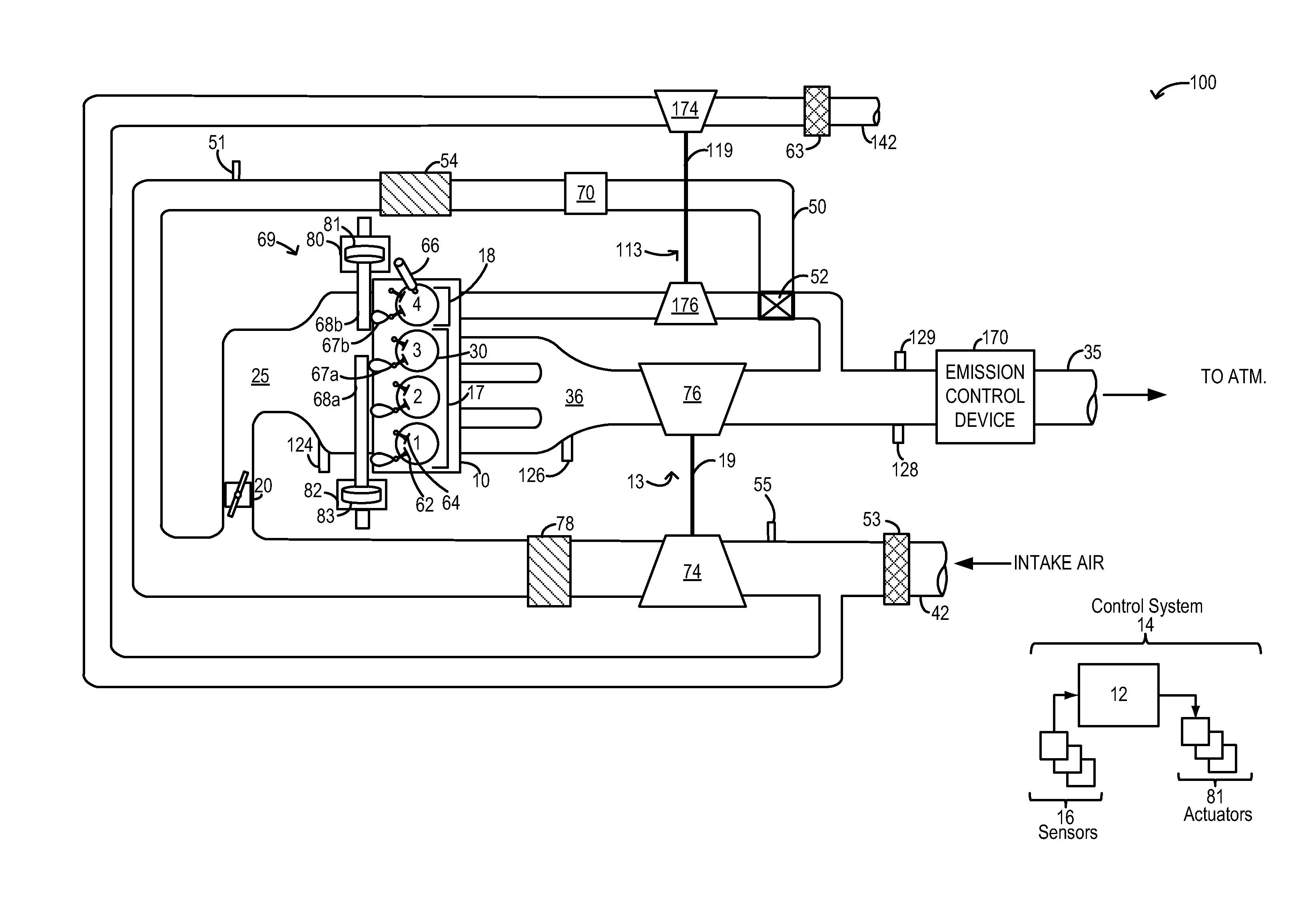
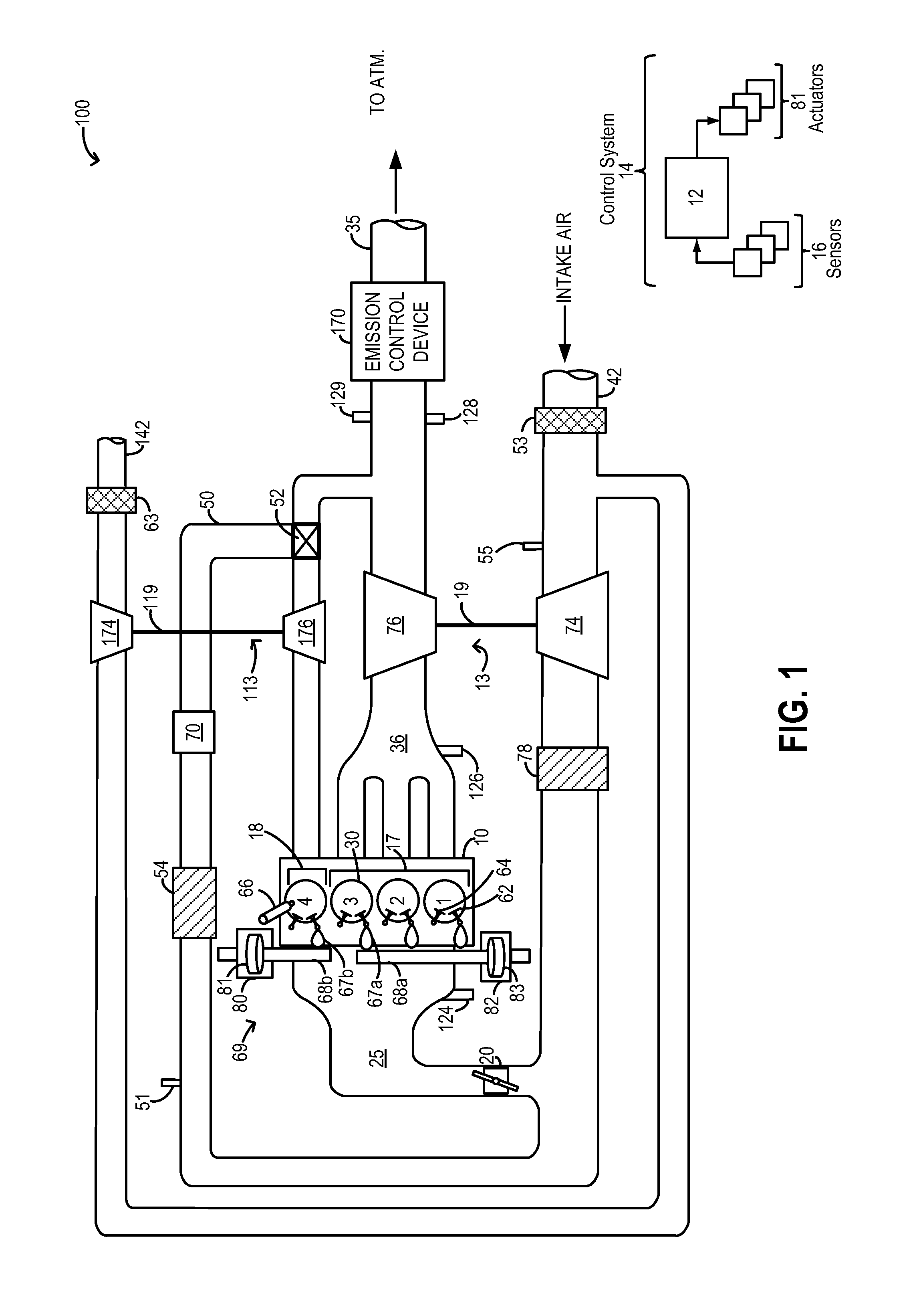
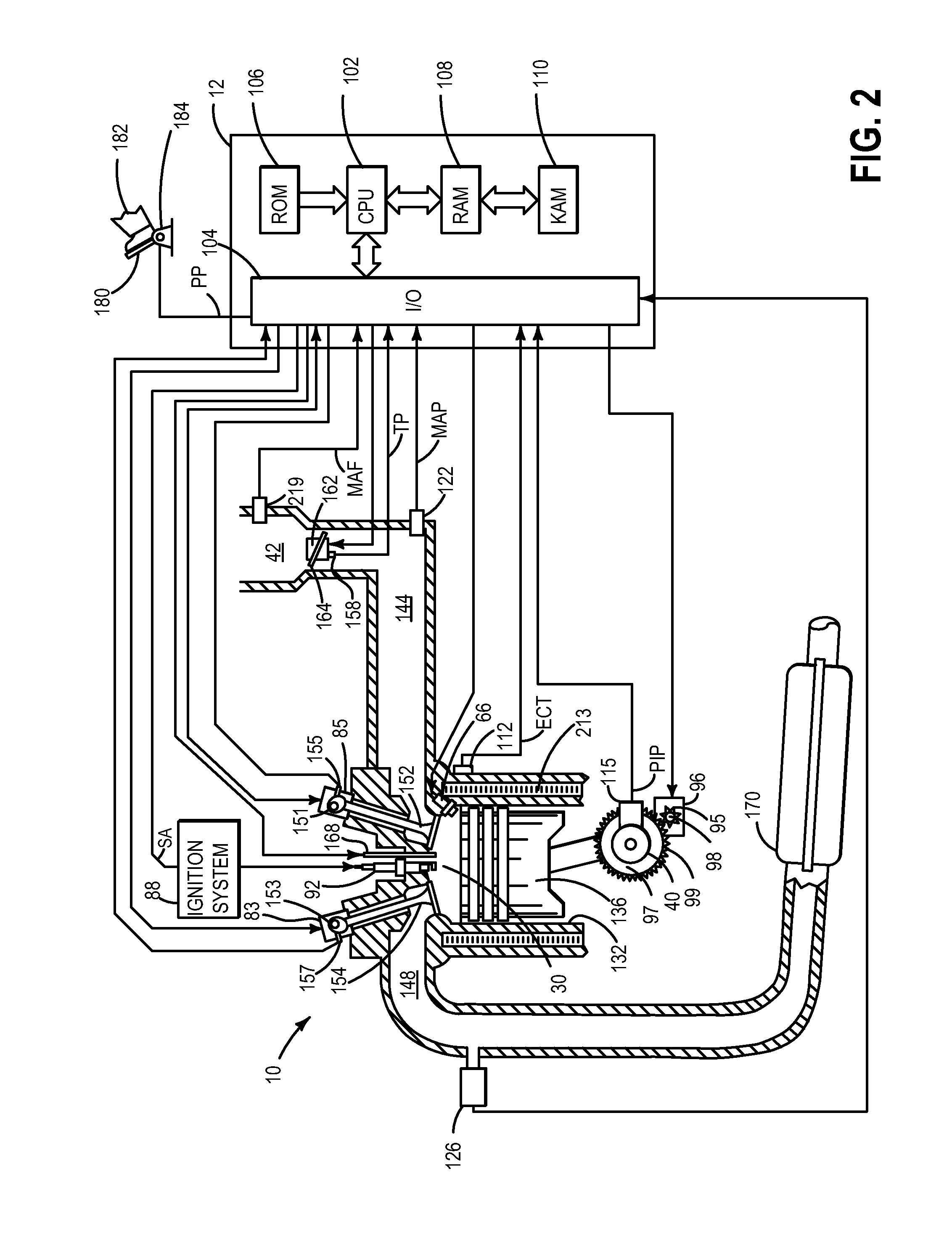
[0019]The present description is related to boost control on an engine operating with highly diluted cylinder mixtures, such as the engine systems of FIGS. 1-2. The engine cylinder mixtures may be diluted using recirculated exhaust gases (EGR) that are byproducts of combusting air-fuel mixtures. A controller may be configured to perform a control routine, such as the routine of FIG. 3, to operate a dedicated EGR cylinder group with rich fuel combustion and increased blow-through air in response to an increase in boost demand. Example air-fuel profiles that may be applied to the dedicated EGR cylinder group are shown at FIG. 4. The controller may also perform a routine, such as the routine of FIG. 5, to adjust a target air-fuel ratio of combustion of the dedicated EGR cylinder group in response to an increase in boost demand, such as during a tip-in event, to expedite turbine spin-up. In this way, turbo lag can be addressed while continuing to provide EGR at high boosted conditions. ...


PUM


Abstract

Methods and systems are provided for reducing turbo lag in an engine system configured with a cylinder dedicated for exhaust gas recirculation and distinct turbines coupled to the dedicated EGR cylinder and remaining engine cylinders. An air-fuel ratio of combustion in the dedicated cylinder is adjusted responsive to a tip-in event by providing blow-through air and additional fuel based on the amount of heat required to spin up a turbine coupled to the dedicated cylinder and provide the requested boost pressure. The approach enables turbo lag to be reduced while providing high EGR at high boost conditions.

Description

FIELD[0001]The present description relates to systems and methods for improving boost control in engine systems configured with a sole cylinder for providing external EGR to other engine cylinders.BACKGROUND AND SUMMARY[0002]Engines may be configured with exhaust gas recirculation (EGR) systems to divert at least some exhaust gas from an engine exhaust manifold to an engine intake manifold. By providing a desired engine dilution, such systems reduce engine knock, throttling losses, as well as NOx emissions. In addition, fuel economy is improved, especially at higher levels of engine boost.[0003]Engines have also been configured with a sole cylinder (or cylinder group) that is dedicated for providing external EGR to other engine cylinders. Additionally, internal combustion engines often include a turbocharger assembly. The turbocharger assembly uses the flow of exhaust gas to spin a turbine, which in turn drives a compressor that compresses the combustion air that is supplied to the ...

Claims


Application Information

Patent Timeline
IPC IPC(8): F02M25/07F02B47/08
CPCF02B47/08F02M25/0749F02B37/001F02B37/007F02B2075/125F02D13/0261F02D41/0007F02D41/008F02D2041/001F02M26/01F02M26/08F02M26/43Y02T10/12F02M35/108
Inventor GLUGLA, CHRIS PAUL
Owner FORD GLOBAL TECH LLC
Why Eureka
Try Eureka