Supercharge Your Innovation With Domain-Expert AI Agents!

Boost circuits, LED backlight driving circuits and liquid crystal devices

a backlight driving circuit and boost circuit technology, applied in the direction of electric variable regulation, process and machine control, instruments, etc., can solve the problems of low lighting efficiency, single boost line can only obtain one output voltage, and ccfl needs a long time, so as to reduce the cost of the product

Active Publication Date: 2015-12-17
SHENZHEN CHINA STAR OPTOELECTRONICS TECH CO LTD
View PDF14 Cites 0 Cited by
  • Summary
  • Abstract
  • Description
  • Claims
  • Application Information

AI Technical Summary

Benefits of technology

The LED backlight driving circuit described in this patent uses a boost circuit with one input voltage to generate multiple output voltages. This allows for energy efficient use of voltage, even though multiple output voltages may be needed. The circuit can supply not only the LED string, but also other loadings of the driving circuit. This eliminates the need for large-scale energy-saving components, reducing product costs.

Problems solved by technology

However, as the CCFL backlight is characterized by attributes including low color reduction ability, low lighting efficiency, high discharging voltage, bad discharging characteristics in low temperature, and also, the CCFL needs a long time to achieve a stable gray scale, LED backlight source is a newly developed technology.
Currently, a single boost line can only obtain one output voltage.

Method used


Image

  • Boost circuits, LED backlight driving circuits and liquid crystal devices
  • Boost circuits, LED backlight driving circuits and liquid crystal devices
  • Boost circuits, LED backlight driving circuits and liquid crystal devices

Examples


Embodiment Construction

[0021]Embodiments of the invention will now be described more fully hereinafter with reference to the accompanying drawings, in which embodiments of the invention are shown.

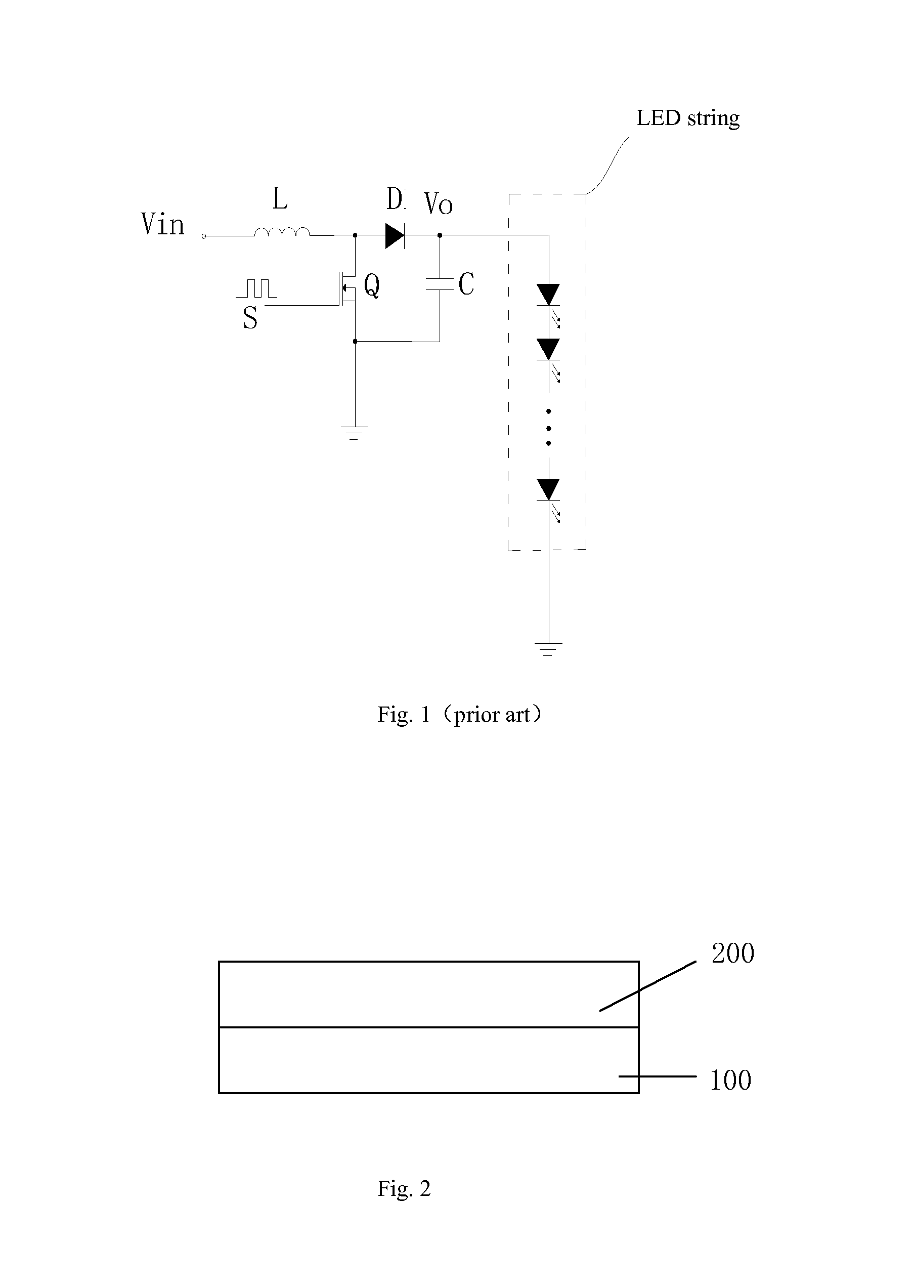
[0022]As shown in FIG. 2, the LCD includes a liquid crystal panel 200 and a backlight module 100 for providing a display light source to the liquid crystal panel 200 such that the liquid crystal panel 200 may display images. The backlight module 100 includes a LED backlight source.

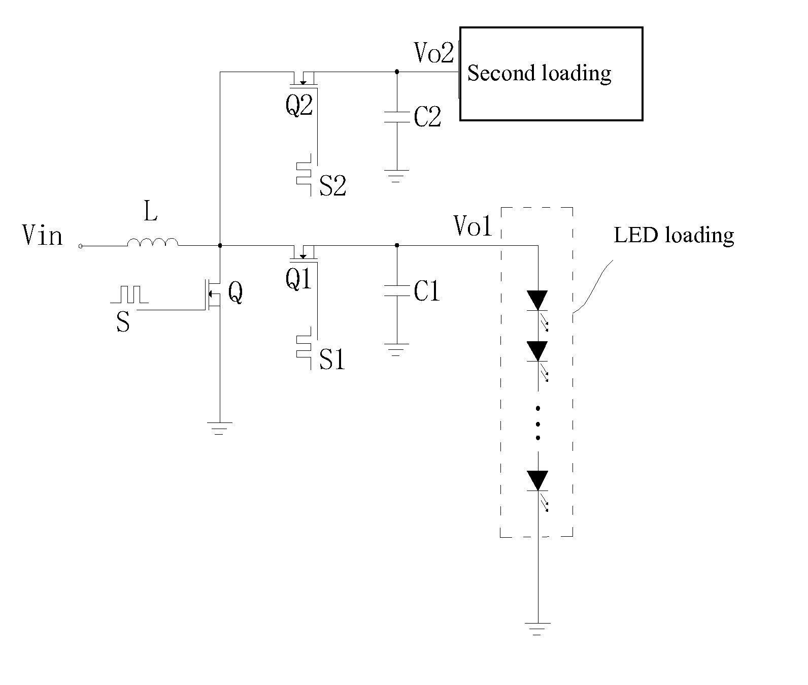
[0023]The driving circuit of the LED backlight source includes a boost circuit for converting an input voltage to a plurality of output voltages so as to provide operational voltages to a plurality of loadings, such as the LED string, the operational voltage (Vcc), the reference voltage (Vref), and so on, of the driving circuit.

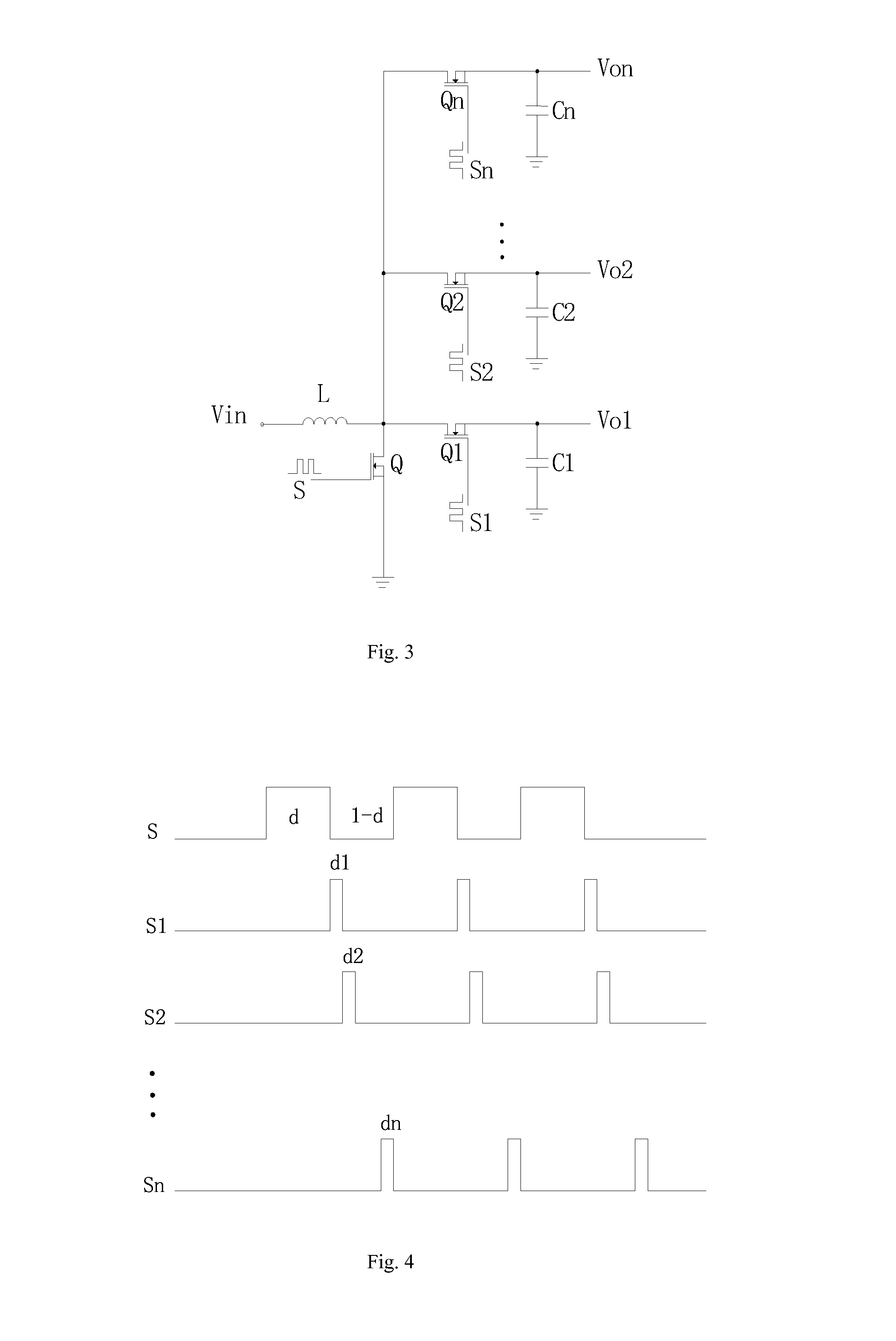
[0024]As shown in FIG. 3, the boost circuit includes an inductor (L), a MOS transistor (Q), and a number “n” of switch components (Q1-Qn). A first end of the inductor (L) receives an input voltage (Vin), and a se...


PUM


Abstract

A boost circuit includes an inductor (L), a MOS transistor (Q), and a number “n” of switch components (Q1-Qn) is disclosed. A first end of the inductor (L) receives an input voltage (Vin), and a second end of the inductor (L) connects to a drain of the MOS transistor (Q). A source of the MOS transistor (Q) is electrically grounded, and a gate of the MOS transistor (Q) is driven by one square-wave signals (S). The number “n” of switch components respectively connects to the inductor and respectively outputs a number “n” of output voltages. The number “n” of switch components are driven by a number “n” of square-wave signals (S1-Sn). A duty ratio of the square-wave signals (S) is d, and the duty ratios of the square-wave signals (S1-Sn) are d1-dn. Before a turn-off time of each period of the MOS transistor (Q), the number “n” of square-wave signals (S1-Sn) are driven by a number “n” of switch components (Q1-Qn) in turn. Wherein d1+d2+d3+ . . . +dn=1−d, and n is an integer greater than one. In addition, a LED backlight driving circuit and a liquid crystal device having the above boost circuit are disclosed.

Description

BACKGROUND OF THE INVENTION[0001]1. Field of the Invention[0002]The present disclosure relates to boost circuit technology, and more particularly to a boost circuit having one input voltage and a plurality of output voltages, the LED backlight driving circuit with the boost circuit, and the liquid crystal device (LCD) with the LED backlight driving circuit.[0003]2. Discussion of the Related Art[0004]With the technology revolution, backlight technology of LCDs has been developed. Typical LCDs adopt cold cathode fluorescent lamps (CCFL) as the backlight sources. However, as the CCFL backlight is characterized by attributes including low color reduction ability, low lighting efficiency, high discharging voltage, bad discharging characteristics in low temperature, and also, the CCFL needs a long time to achieve a stable gray scale, LED backlight source is a newly developed technology. For LCDs, the LED backlight source is arranged opposite to the liquid crystal panel so as to provide th...

Claims


Application Information

Patent Timeline
IPC IPC(8): H05B37/02G02F1/1335H02M3/156H02M1/00
CPCH05B37/02Y10T307/406G02F1/133603H02M3/156G09G3/342G09G2320/064G09G2330/024H02M3/158H05B45/38H05B47/10H02M1/009Y02B20/30
Inventor ZHANG, HUALI, FEI
Owner SHENZHEN CHINA STAR OPTOELECTRONICS TECH CO LTD
Features
  • R&D
  • Intellectual Property
  • Life Sciences
  • Materials
  • Tech Scout
  • Unparalleled Data Quality
  • Higher Quality Content
  • 60% Fewer Hallucinations
Learn More