Endotracheal intubation devices

a technology of intubation device and endotracheal tube, which is applied in the field of endoscopic devices, can solve the problems of multiple attempts to use different equipment, inability to unaided visualization of the airway beyond the tongue, and inability to visualize the airway unaided, and achieve the effect of easy separation and easy removal

Active Publication Date: 2015-12-24
RUTGERS RICHARD
View PDF13 Cites 28 Cited by
  • Summary
  • Abstract
  • Description
  • Claims
  • Application Information

AI Technical Summary

Benefits of technology

[0018]As is mentioned above, the present invention may utilize a malleable shaft which allows the medical practitioner to pre-bend the shaft into a desired configuration. This embodiment allows the practitioner to shape the shaft as needed to achieve a configuration that will extend around the varying anatomical features of the patient, allowing the distal end to be placed near the opening of the trachea. Once the steerable distal end is placed “in the ballpark” of the trachea opening, the practitioner then utilizes the visualization components to identify the vocal cords and then steer the distal end of the shaft with its overlying endotracheal tube through the vocal cords and into the trachea. By moving the distal end to an angular position which aligns the endotracheal tube with the opening of the trachea and advancing toward it, the practitioner then only has to move the endotracheal tube into the opening. In one aspect, the shaft can be made from a malleable tubing. Alternatively, a malleable rod can be inserted into the inner lumen of the shaft to provide the stiffness needed to maintain the shaft in its pre-shaped configuration.
[0019]The tongue retractor of the present invention can be made into a curved conduit in various shapes and sizes to accommodate patients of different size and age. Alternatively, the retractor can be made from a malleable material which allows the practitioner to pre-bend it to a desired shape. As is mentioned above, the tongue retractor is attached to a handle by means of which it can be moved while inside the pharynx into different positions. The endoscope can then be advanced through the conduit formed by the retractor, which has moved the tongue out of the way, and identifies the vocal cords and is guided into the trachea. In one aspect of the present invention, the retractor includes an upper shell releasably connected to a lower shell. After the endotracheal tube is placed, the tongue retractor can be removed from the patient. However, if the retractor applies force to the endotracheal tube as it is being removed, it may pull the endotracheal tube out with it. This is certainly undesirable. In the invention described, the retractor can be made from two shells releasably connected together, the retractor can be easily split apart, thereby creating two pieces which can be more easily removed from the patient's oral cavity without applying friction to the endotracheal tube and dislodging it. In another aspec

Problems solved by technology

Human anatomy does not permit unaided visualization of the airway beyond the tongue.
In practice, however, there may be anatomical anomalies and physical variations among patients which often do not permit easy direct visualization of the vocal cords.
This leads to multiple attempts using different equipment.
Failure to establish an airway in critically ill or anesthetized patients may lead to hypoxia (lack of oxygen), brain damage or even death in five minutes.
While identification of the vocal cords under direct vision as described above is normally routine, there may be internal anatomical or pathological obstructions that are not apparent on visual inspection of the patient's surface anatomy.
Multiple attempts at intubation may result in injury to teeth, epiglottis and vocal cords.
Bleeding may result, with even less ability to visualize the airway and sometimes to obstruction of the airway, leading to hypoxia.
Because it is and invasive and extremely uncomfortable procedure, intubation is most frequently performed after induction of general anesthesia.
However, this means that the patient has now lost his ability to breathe spontaneously and therefore ventilation must be supported by the practitioner.
At this point inability to intubate or provide ventilation of the lungs can lead to grave consequences, and is the lea

Method used


Image

  • Endotracheal intubation devices
  • Endotracheal intubation devices
  • Endotracheal intubation devices

Examples


Embodiment Construction

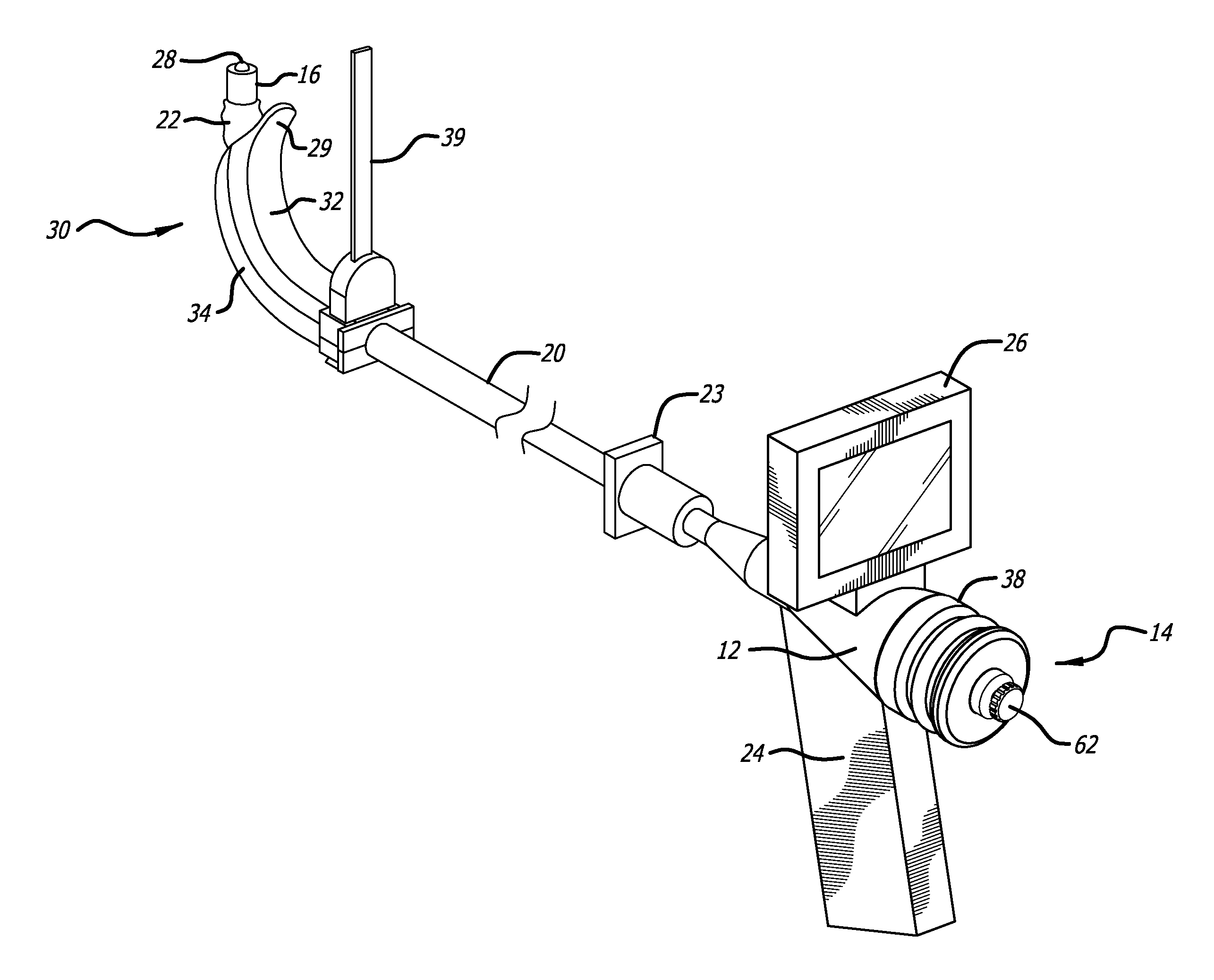
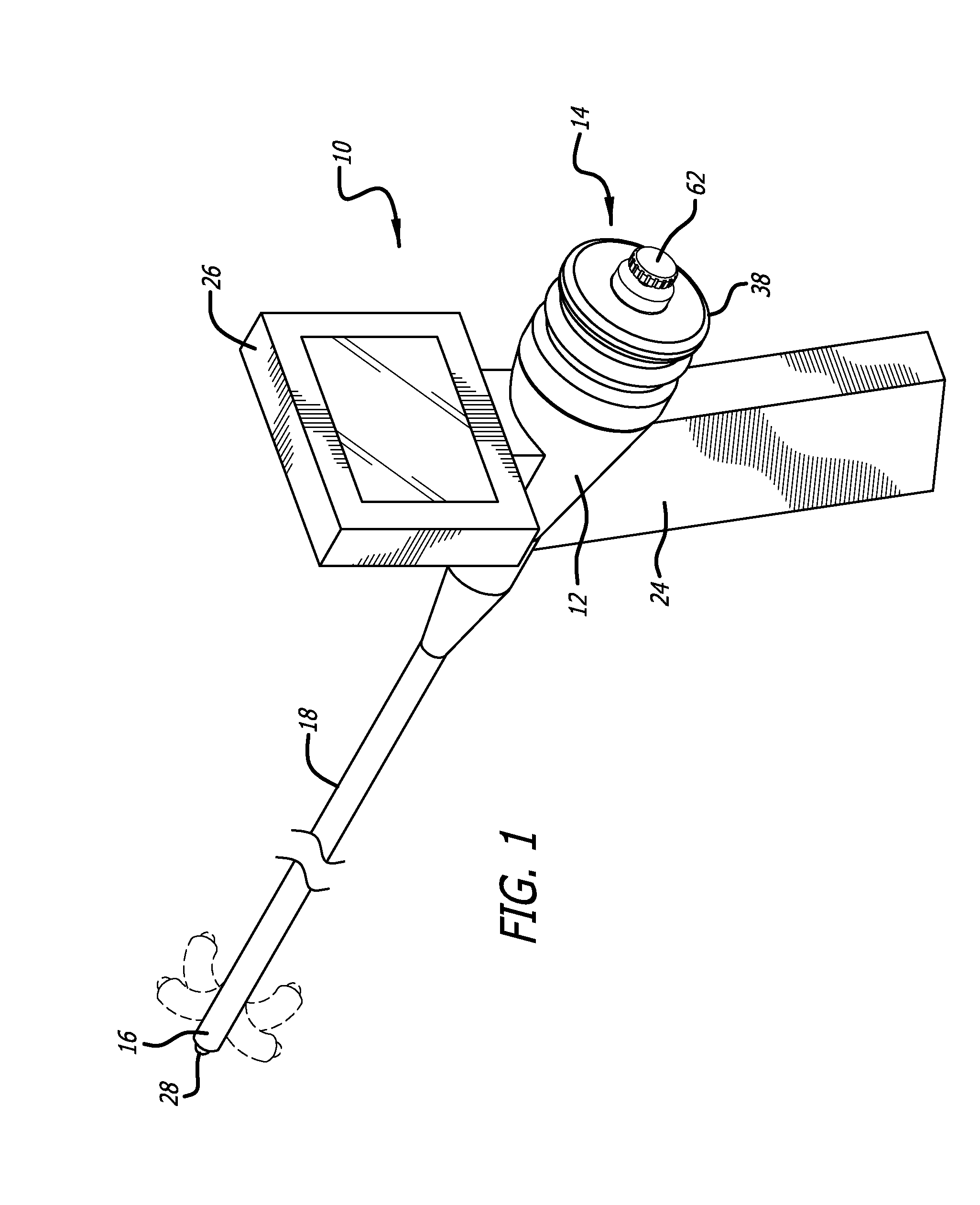
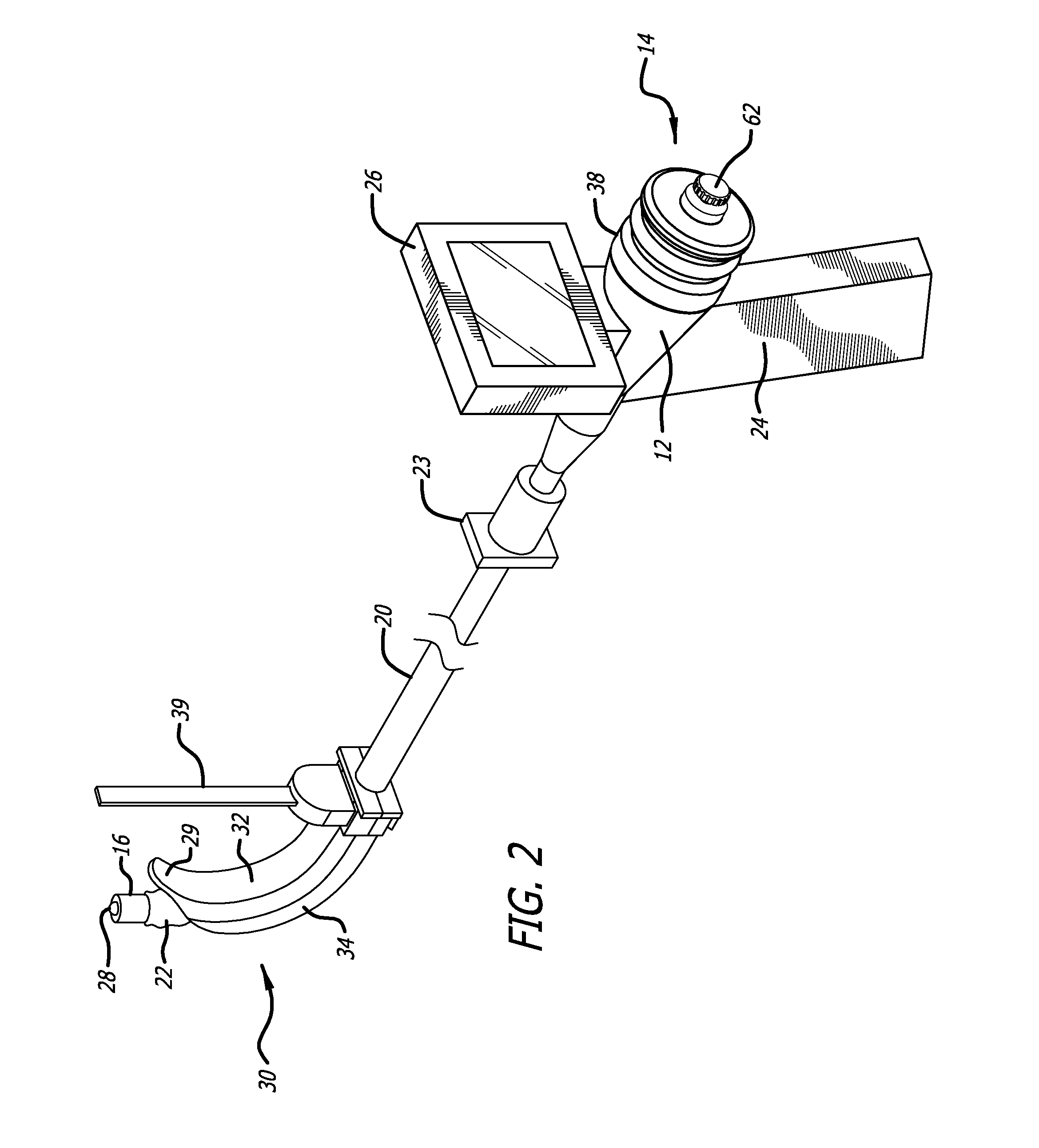
[0061]Embodiments of devices made in accordance with the present invention will now be described in detail with reference to the accompanying drawings. Referring initially to FIGS. 1 and 2, a hermetically-sealed endoscope 10 made in accordance with the present invention includes an outer casing 12 which houses a steering control mechanism 14 that can be manually manipulated to steer the distal end 16 of a flexible or malleable shaft 18 to a number of different angular positions. The steerable distal end 16 is shown in its neutral position (where the distal end is substantially straight) which maximizes the number of different angular positions that can be taken achieved. Just a few of the numerous angular positions that can be attained by the distal end 16 are represented by dotted lines appearing in FIG. 1. A removable endotracheal tube 20 (FIG. 2) with an inflatable balloon cuff 22 located at its distal end and a t-piece fitting 23 at its proximal end can be placed co-axially over...


PUM


Abstract

The endoscope herein described has a unique steering capability allowing the highly flexible distal end of the shaft of the device to be moved to a full range angular positions without rotating the device on its long axis, thus enabling the device to be steered within the cavity of interest. The relative lengths of the control cables used to move the distal end of the bendable shaft can be changed whenever the flexible or malleable shaft is to be re-shaped to a new configuration thus preventing the distal end or the steering mechanism from assuming an undesired angular position. When used as an endotracheal device, a novel tongue retractor is described which forms an internal conduit, allowing passage of the bendable shaft of the endotracheal intubation device and an endotracheal tube therethrough. Methods for performing a tracheal intubation and changing the relative lengths of the cables are disclosed.

Description

CROSS-REFERENCES TO RELATED APPLICATIONS[0001]The present application claims the benefit under 37 CFR §119(e) of U.S. Provisional Application No. 61 / 791,596 filed on Mar. 15, 2013, and to PCT / US / 2014025642 filed Mar. 13, 2014, the contents of which are incorporated by reference herein in their entirety.BACKGROUND[0002]The present invention relates generally to endoscopic devices and, more specifically, to an endotracheal intubation device having steering capability to allow the steerable distal end of the shaft of the device to be moved to a number of different angular positions to help direct the device through normal and pathologic patient anatomy. In use, an endotracheal tube is co-axially placed over the shaft of the endotracheal device so that the distal end of the endotracheal tube can be properly inserted into the trachea. The shaft of the current device may be of different rigidities, i.e., either flexible, like a conventional endoscope (colonoscope, bronchoscope, etc.) or m...

Claims


Application Information

Patent Timeline
IPC IPC(8): A61B1/267A61B1/005A61B1/06A61M16/04A61B1/00
CPCA61B1/267A61M16/0434A61M16/0495A61B1/00052A61B1/0676A61B1/005A61B1/00096A61M16/0488A61M16/0418A61B1/0052A61B1/00066A61B1/0057A61B1/2676A61M25/0147A61B2017/00318A61M25/0133A61B2017/00323A61M25/0136
Inventor RUTGERS, RICHARD P.
Owner RUTGERS RICHARD
Why Eureka
Try Eureka