System for measurement of cardiovascular health

a cardiovascular health and monitoring system technology, applied in the field of diagnostic and monitoring of cardiovascular health, can solve the problems of major global health problems, invasive means run the serious risks of arterial injury and infection, and cuff sphygmomanometry can be uncomfortabl

Inactive Publication Date: 2015-12-24
CNV SYST
View PDF1 Cites 92 Cited by
  • Summary
  • Abstract
  • Description
  • Claims
  • Application Information

AI Technical Summary

Benefits of technology

[0055]All of the components of the system are synchronized and function on a continuous basis over an extended period of time so as to determine an individual's relative trending markers over time and avoid the requirement for secondary calibration with outside systems. The system is designed with comfort, portability, long-term wear, and use during regular, daily-life activities in mind. There are no external wires, and the system is completely housed in comfortably worn devices that do not draw attention and do not interfere with human motion or dexterity. Such monitoring over time also allows for sustained biometric measurements, leading to clarification of an individual user's biometric signature, from which abnormalities in the rate of circulatory degeneration can be determined and applicable preventive measures applied potentially before a health crisis occurs.

Problems solved by technology

Cardiovascular disease is the leading killer in the world and represents a major global health problem.
While relatively simple to use, cuff sphygmomanometry can be uncomfortable, and only generates one point of data at the time of use.
It can also be inaccurate for various reasons, including emotional state at the time of use, time of day, and user judgment error.
While more accurate and capable of continuously monitoring blood pressure, invasive means run the serious risks of arterial injury and infection.
However, BP in and of itself does not provide a complete measure for a particular individual's health, as BP values and health effects vary greatly between individuals.
Also, it is difficult to achieve truly precise fixed systolic / diastolic values using the BP measuring devices known in the art.
These devices tend to provide estimates only, and are non-continuous, momentary spot measurements that are subject to the effects of the individual's emotional and environmental circumstances at the time the measurement is taken.

Method used


Image

  • System for measurement of cardiovascular health
  • System for measurement of cardiovascular health
  • System for measurement of cardiovascular health

Examples


first embodiment

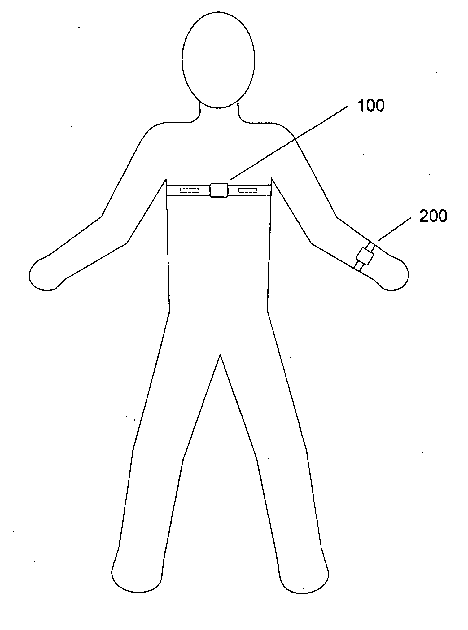
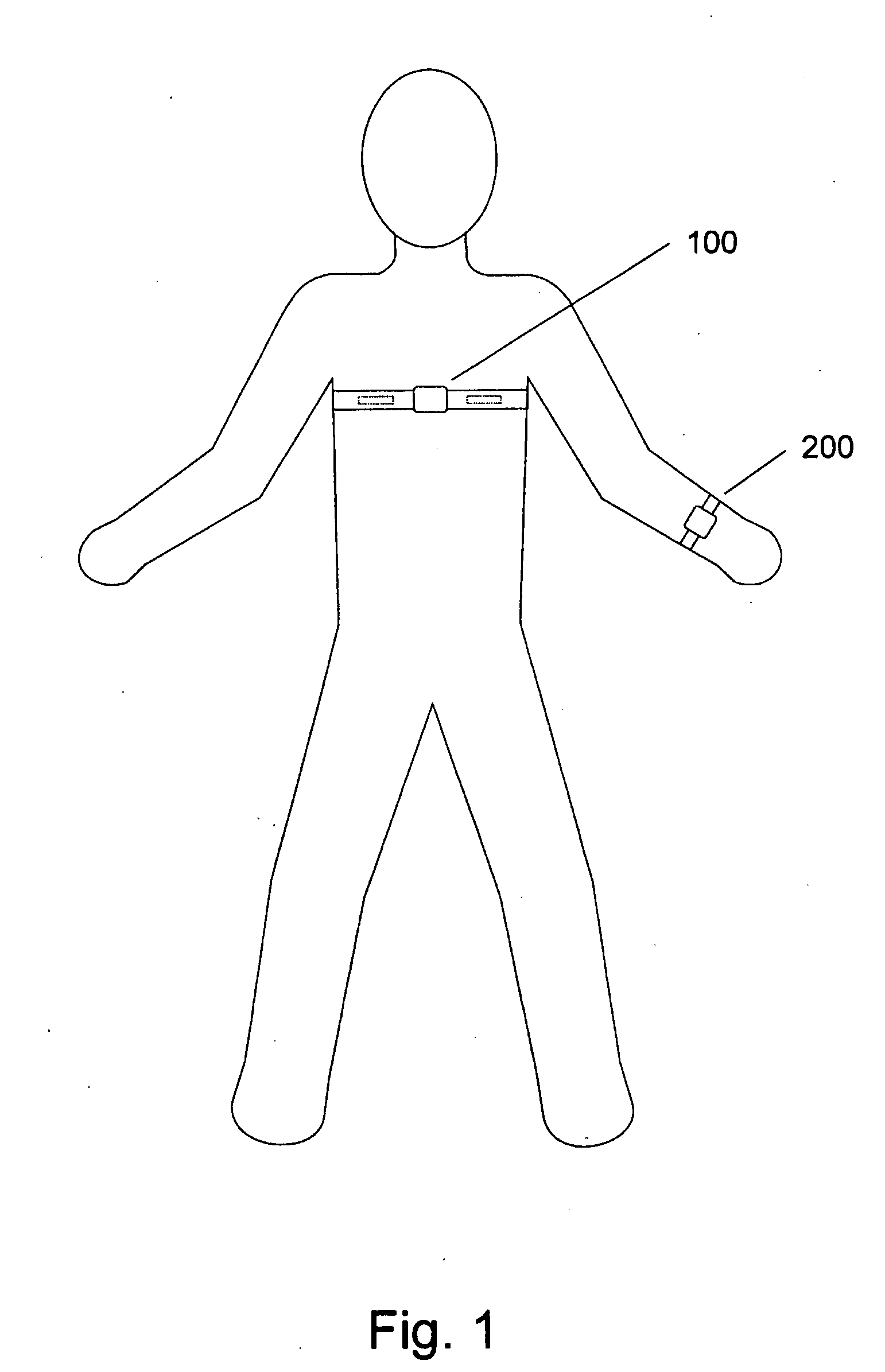
[0082]In the invention, there is a chest strap ECG source (100) strapped around the chest of a person, and a wrist-worn device (200) worn around the wrist of the same person, as shown in FIG. 1.

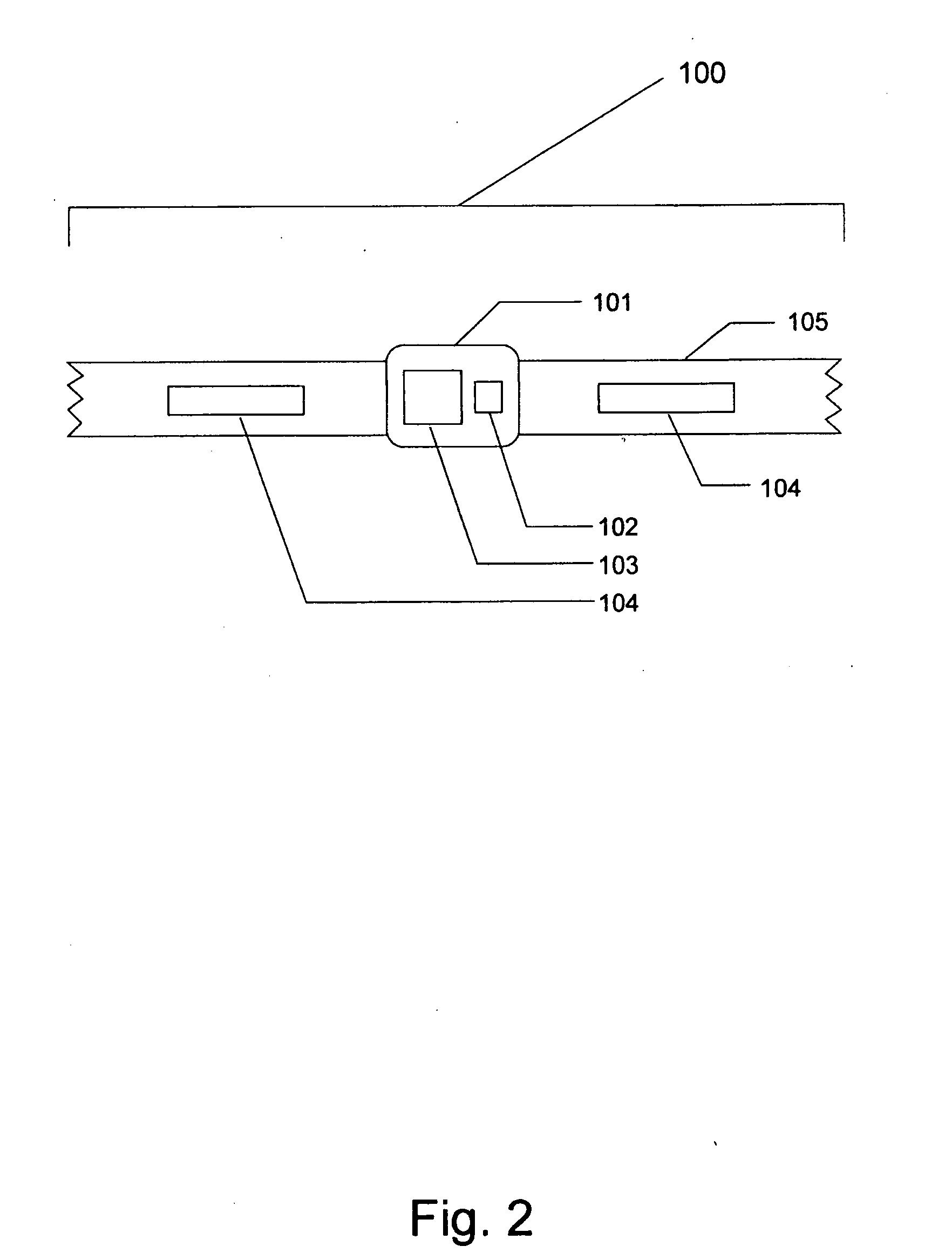
[0083]In the first embodiment, the chest strap ECG source (100) has the following components: ECG housing (101), ECG circuitry (103), elastic strap (105), wireless transmitter (102), and electrode contact strips (104), as shown in FIG. 2. The ECG circuitry (103) and wireless transmitter (102) are housed within the centrally located ECG housing (101). The elastic strap (105) extends from two opposing sides of the ECG housing (101) to strap around the wearer. When the ECG source (100) is worn, the electrode contact strips (104) on the elastic strap (105) make contact with the skin of the chest of the wearer.

[0084]Such basic ECG chest straps are known in the art and are commercially available. In the first embodiment, the ECG chest strap is modified with BTLE wireless communication.

[0085]In the ...

second embodiment

[0095]In a second embodiment, rather than a chest-worn ECG source, the ECG signal and data is obtained via two contact ECG electrodes (309) on the wrist-worn device (200) itself. As shown in FIG. 8, a first contact electrode (309) surrounds the display screen (202) on the front of the wrist-worn device (200), while a second contact electrode (not directly visible in FIG. 8) is placed on the back plating of the wrist-worn device (200) alongside the LEDs (207) and the optic sensor (208). The second contact electrode is in constant contact with the skin of the wrist while the wrist-worn device (200) is worn, while the first contact electrode (309) may be touched with a finger to complete the circuit and obtain an ECG signal and data.

[0096]Corresponding to this second, touch ECG embodiment, an internal schematic is depicted in FIG. 9. The schematic for this touch ECG embodiment is essentially identical to the FIG. 7 schematic, except the separate chest-strap ECG source (100) is replaced...


PUM


Abstract

A system that continuously monitors cardiovascular health using an electrocardiography (ECG) source synchronized to an optical (PPG) source, without requiring invasive techniques or ongoing, large-scale external scanning procedures. The system includes an ECG signal source with electrodes contacting the skin, which generates a first set of information, and a watch-like device, worn on a limb such as an arm or a wrist, having a reflectance-based PPG signal source that generates a second set of information. Together with a processing module, housed within the watch-like device and configured to receive and process the first and second sets of information, from which the time differential of the heart beat pulmonary pressure wave can be calculated, continuous data related to cardiovascular health markers such as arterial stiffness can be determined. Automated heart rate calibration of the reflectance-based PPG sensor can also be achieved.

Description

PATENT REFERENCES CITED[0001]U.S. Pat. No. 8,162,841[0002]U.S. Pat. No. 7,674,231[0003]US 2004 / 0030261[0004]U.S. Pat. No. 7,179,228[0005]U.S. Pat. No. 7,479,111[0006]U.S. Pat. No. 7,481,772[0007]U.S. Pat. No. 7,544,168[0008]U.S. Pat. No. 7,803,120[0009]U.S. Pat. No. 7,993,275[0010]U.S. Pat. No. 7,029,447[0011]U.S. Pat. No. 6,736,789[0012]U.S. Pat. No. 6,331,162[0013]WO 2012 / 092303OTHER REFERENCES[0014]Boutouyrie, Pierre et al. “Obtaining arterial stiffness indices from simple arm cuff measurements: the holy grail?”Journal of Hypertension 2009, 27:2159-2161.[0015]Conlon et al. “Development of a Mathematical Model of the Human Circulatory System”Annals of Biomedical Engineering, Vol. 34, No. 9, September 2006, pp. 1400-1413.[0016]Douniama, C. et al. “Blood Pressure Tracking Capabilities of Pulse Transit Times in Different Arterial Segments: A Clinical Evaluation”Computers in Cardiology, 2009; 36: 201-204.[0017]Fung et al. “Continuous Noninvasive Blood Pressure Measurement by Pulse Tra...

Claims


Application Information

Patent Timeline
Patent Type & Authority Applications(United States)
IPC IPC(8): A61B5/0205A61B5/00A61B5/0402A61B5/332
CPCA61B5/02055A61B5/0402A61B5/0022A61B5/6823A61B5/6824A61B5/6828A61B5/0295A61B5/7275A61B5/02007A61B5/02125A61B5/02416A61B5/14551A61B5/7207A61B5/0245A61B5/0205A61B5/02438A61B5/681A61B5/332A61B5/318
Inventor HARRIS, PAUL RONALDLI, JI FENG
Owner CNV SYST
Why Eureka
Try Eureka