Differential flow-meter for measuring the weight loss in haemodialysis treatments

a flowmeter and weight loss technology, applied in the field of differential flowmeters, can solve the problems of greater measurement accuracy and precision, and achieve the effect of high sensitivity and precision and guaranteeing measurement accuracy

Active Publication Date: 2015-12-24
MEDICA
View PDF5 Cites 0 Cited by
  • Summary
  • Abstract
  • Description
  • Claims
  • Application Information

AI Technical Summary

Benefits of technology

[0027]The present invention develops a differential system directly measuring the difference between the two flows (weight loss) by using the principle of the “thermal anemometer” in order to obtain high sensitivity and precision and to guarantee the measurement accuracy.

Problems solved by technology

This implies a major constructive simplification, resulting in a limitation of the geometric nonidealities, thus obtaining greater measurement accuracy and precision.

Method used


Image

  • Differential flow-meter for measuring the weight loss in haemodialysis treatments
  • Differential flow-meter for measuring the weight loss in haemodialysis treatments
  • Differential flow-meter for measuring the weight loss in haemodialysis treatments

Examples


Embodiment Construction

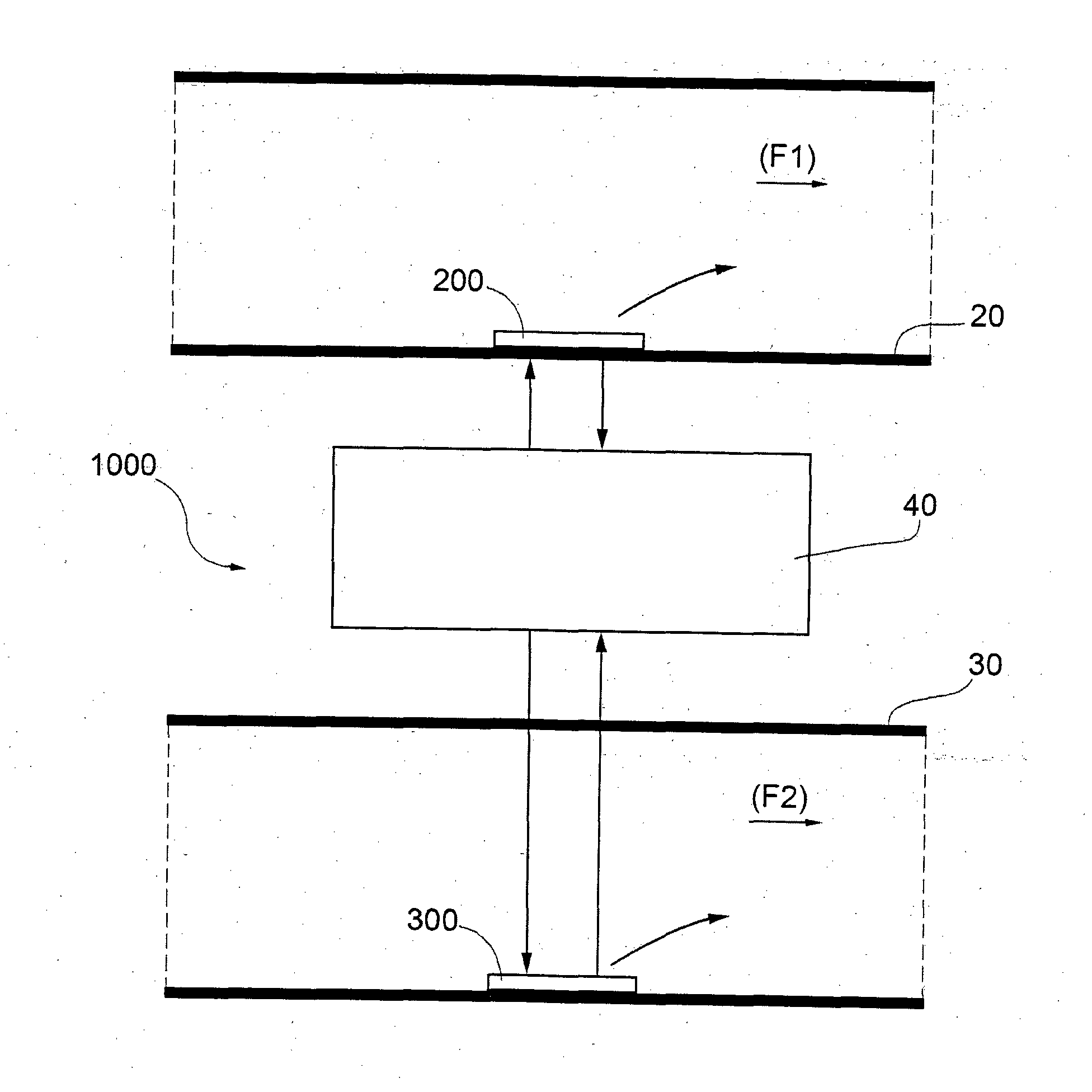
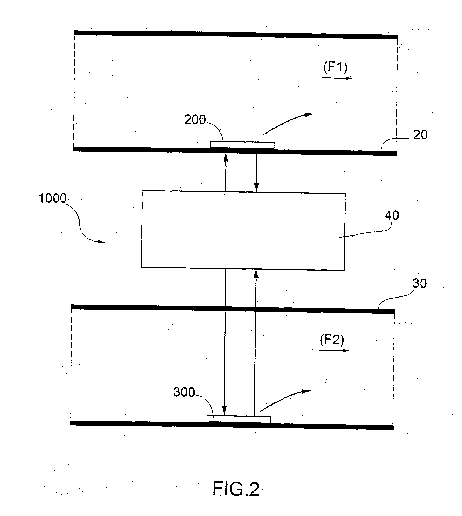
[0038]In FIG. 21000 indicates, as a whole, a differential flow-meter using the principle of the thermal anemometer flow-meter, which is one of the objects of the present invention.

[0039]The differential flow-meter 1000 comprises a first separate channel 20 and a second separate channel 30 in which two fluids flow, said fluids being same or different.

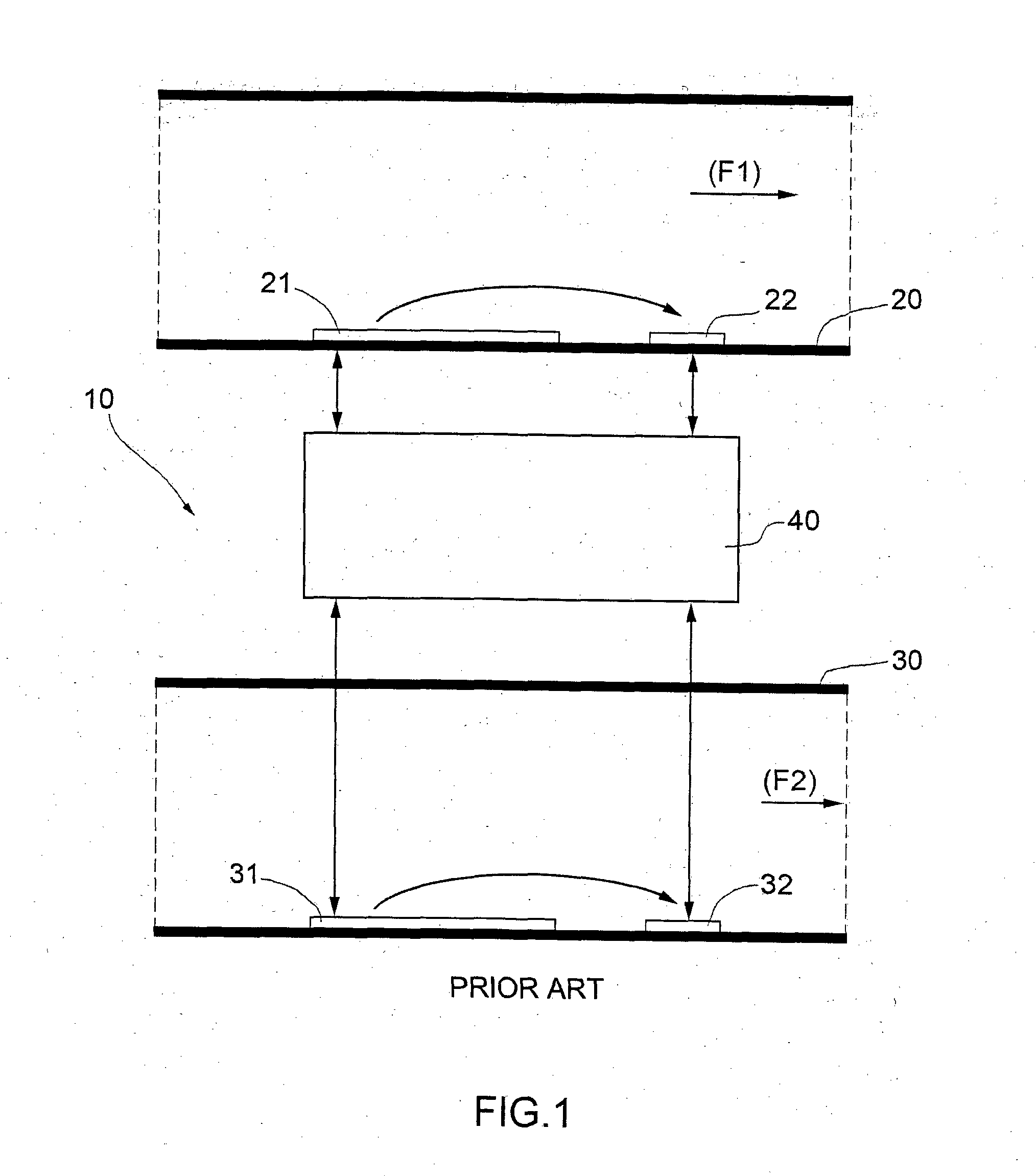
[0040]A thermal device 200 is attached on the inner wall of channel 20. In said device 200, the temperature sensor 22 seen in FIG. 1 corresponds in principle to the heating plate 21. In particular, it is a resistor overheated thanks to the Joule effect, namely by imposing a suitably high current, with the resulting resistance increase, said resistor being cooled by the moving fluid, with the resulting temperature decrease. Therefore this resistance variation is inversely proportional to the fluid flow rate.

[0041]Analogously, a thermal device 300 is attached on the inner wall of channel 30. In said device 300, the temperature sensor 32 se...


PUM


Abstract

A differential flow-meter for measuring the weight loss in dialysis treatments. The differential flow-meter is of the “thermal anemometer” type.

Description

TECHNICAL FIELD[0001]The present invention concerns a differential flow-meter for measuring the difference of flow rate, or speed, between two fluids.[0002]In particular, the present invention finds an advantageous application in the calculation of weight loss in haemodialysis treatmentsBACKGROUND ART[0003]As already known, more than two million people in the whole world are presently affected by a chronic renal failure, with an annual growth rate close to 6%.[0004]Currently, patients who do not undergo a kidney transplantation are treated by haemodialysis (or extracorporeal dialysis) or by peritoneal dialysis, which replaces the cleaning function of kidneys.[0005]In both these treatments, blood is in contact with a special solution (called “dialysis fluid” or “dialysate”) through a semipermeable membrane.[0006]In haemodialysis, the blood purification takes place out of the body, inside a special filter, the dialyzer, whereas peritoneal haemodialysis uses the peritoneum natural memb...

Claims


Application Information

Patent Timeline
Patent Type & Authority Applications(United States)
IPC IPC(8): A61M1/14G01F1/684
CPCA61M1/14A61M2205/3393G01F1/684A61M1/3663A61M2205/3334A61M2205/3368A61M1/1601G01F1/6845A61M1/1647G01F1/69
Inventor BELLEI, MARCOBAGNOLI, DAVIDEFECONDINI, LUCIANO
Owner MEDICA
Why Eureka
Try Eureka