Travel control device of hybrid vehicle

a technology of hybrid vehicles and control devices, applied in road transportation, instruments, gearing, etc., can solve the problems of wasteful energy consumption and wasteful energy consumption with load generated, and achieve the effects of reducing energy loss, improving power transmission efficiency in the vehicle, and suppressing power circulation

Active Publication Date: 2015-12-24
TOYOTA JIDOSHA KK
View PDF5 Cites 3 Cited by
  • Summary
  • Abstract
  • Description
  • Claims
  • Application Information

AI Technical Summary

Benefits of technology

[0008]According to the travel control device of the invention, since the rotation speed of either the first motor generator or the second motor generator becomes zero at the time of the acceleration travel, it is possible to suppress the occurrence of power circulation at the time of the acceleration travel. With this, it is possible to reduce energy loss in the motor generator in which the rotation speed becomes zero. Furthermore, it is possible to improve power transmission efficiency in the vehicle. For this reason, it is possible to improve the total energy efficiency of the vehicle and to improve fuel efficiency.
[0009]In the travel control device according to above embodiment, the control means may include deceleration adjustment means for, when the requested speed is higher than a predetermined upper limit speed set in advance, controlling the operation of the second motor generator such that deceleration is equal to or lower than predetermined allowable deceleration at the time of the coasting travel. Since the higher the speed (vehicle speed) of the vehicle, the grater the travel resistance, the deceleration at the time of coasting travel becomes greater. If the deceleration becomes excessively great, the driver may feel a sense of discomfort. According to this embodiment, when the requested speed is higher than the upper limit speed, since the deceleration is equal to or lower than the allowable deceleration, it is possible to suppress a sense of discomfort to the driver.
[0010]In the travel control device according to above embodiment, the first motor generator and the second motor generator may be electrically connected to a battery, and the control means may include charging control means for, when the operation of the second motor generator is controlled by the deceleration adjustment means such that deceleration is equal to or lower than the allowable deceleration at the time of the coasting travel, causing the first motor generator to function as a generator at the time of the acceleration travel and driving the first motor generator with the internal combustion engine to charge the battery. In this way, the battery is charged at the time of the acceleration travel, whereby it is possible to suppress a decrease in the residual quantity of the battery even if electric power is consumed in the second motor generator at the time of the coasting travel.
[0011]In the travel control device according to above embodiment, there is provided a efficiency calculation means for calculating the energy efficiency of the vehicle when it is assumed that the vehicle is allowed to travel in the acceleration/deceleration travel mode and the energy efficiency of the vehicle when it is assumed that the vehicle is allowed to travel in a steady travel mode in which the vehicle is allowed to travel at a constant speed, wherein, when the acceleration/deceleration travel condition is established and the energy efficiency of the vehicle when it is assumed that the vehicle is allowed to travel in the acceleration/deceleration travel mode is greater than the energy efficiency when it is assumed that the vehicle is allowed to travel in the steady travel mode, the control means may control the internal combustion engine, the first motor generator, and the second motor generator such that the vehicle travels in the acceleration/deceleration travel mode. According to this embodiment, since the vehicle is allowed to travel in the acceleration/deceleration travel mode when the energy efficiency during travel of the vehicle in the acceleration/deceleration travel mode is greater than during travel of the vehicle in the steady travel mode, it is possible to further improve the total energy efficiency of the vehicle. For this reason, it is possible to further improve fuel efficiency.
[0012]In the travel control device according to above embodiment, when the requested speed is higher than a predetermined determination speed set in advance, the control means may control the internal combustion engine, the first motor generator, and the second motor generator such that the vehicle travels in a steady travel mode in which the vehicle is allowed to travel at a constant speed even if the acceleration/

Problems solved by technology

For example, so-called power circulation occurs, in which, while the first motor generator generates electric power, the second motor generator consumes electric power dur

Method used


Image

  • Travel control device of hybrid vehicle
  • Travel control device of hybrid vehicle
  • Travel control device of hybrid vehicle

Examples


first embodiment

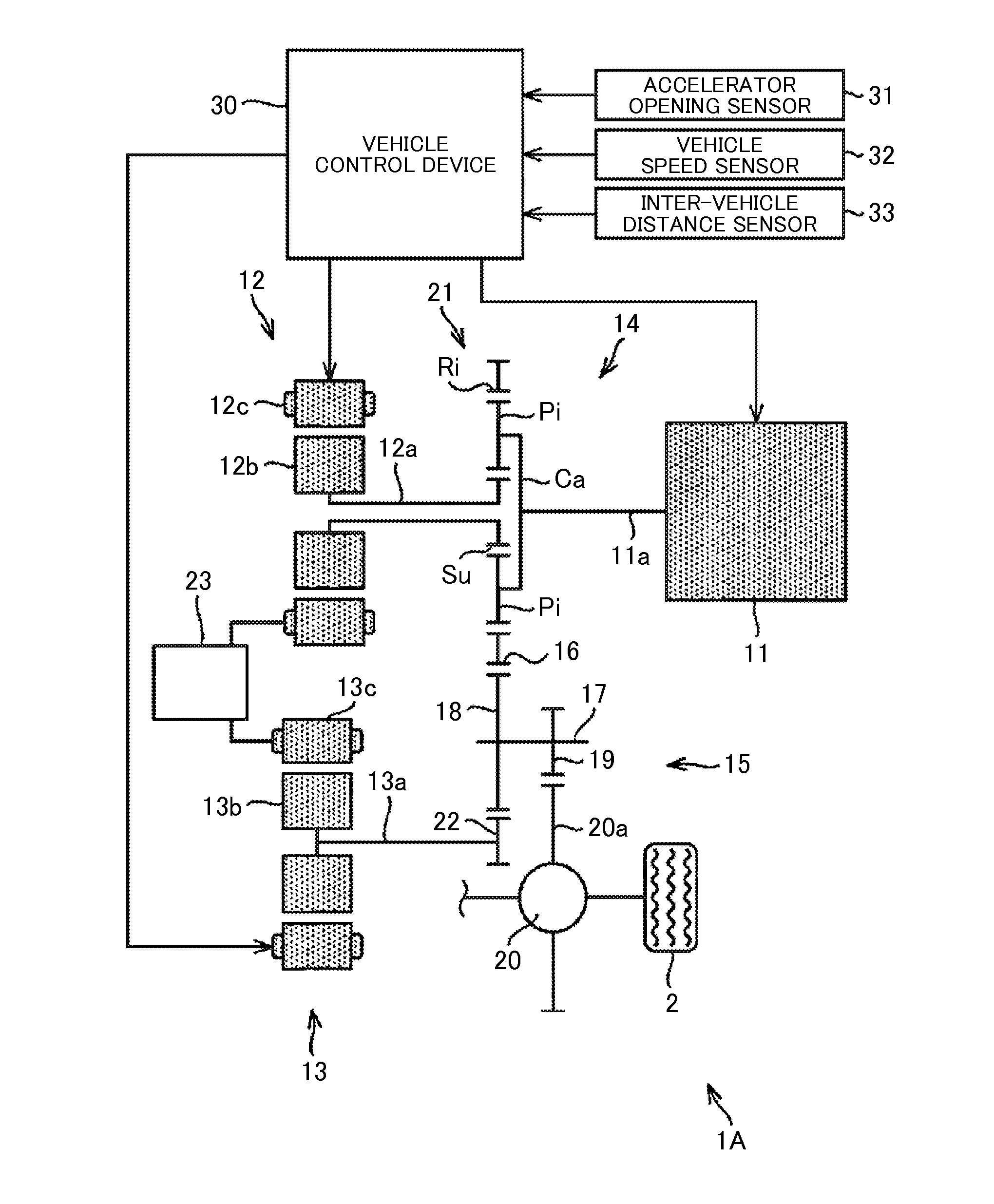
[0035]FIG. 1 schematically shows a vehicle in which a travel control device according to a first embodiment of the invention is incorporated. A vehicle 1A is constituted as a so-called hybrid vehicle. The vehicle 1A includes an internal combustion engine (hereinafter, referred to as an engine) 11, a first motor generator (hereinafter, abbreviated as a first MG) 12, and a second motor generator (hereinafter, abbreviated as a second MG) 13. The engine 11 is a known one which is mounted in the hybrid vehicle, and thus detailed description thereof will be omitted. The first MG 12 and the second MG 13 are known motor generators which function as an electric motor and a generator. The first MG 12 includes a rotor 12b which rotates integrally with an output shaft 12a, and a stator 12c which is arranged coaxially on the outer circumference of the rotor 12b and is fixed to a case (not shown). Similarly, the second MG 13 includes a rotor 13b which rotates integrally with an output shaft 13a, ...

second embodiment

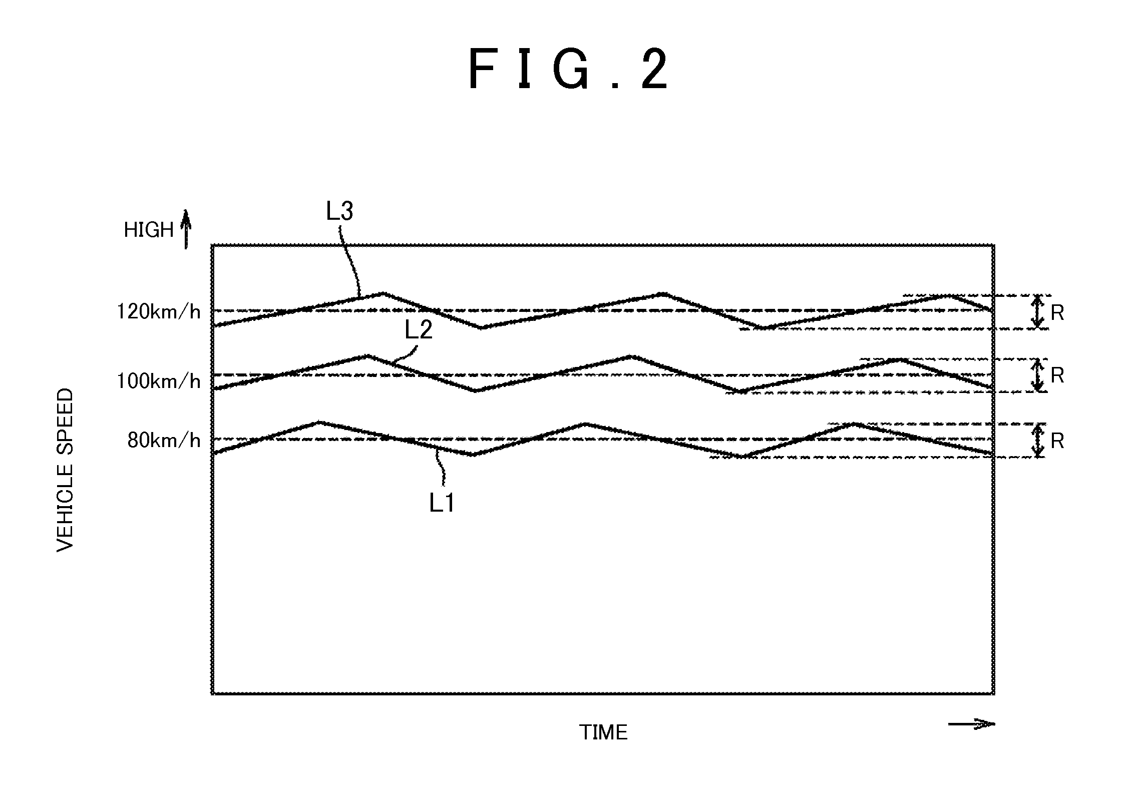
[0050]A travel control device according to a second embodiment of the invention will be described referring to FIGS. 5 to 7. In this embodiment, FIG. 1 is also referred to with regard to the vehicle 1A. FIG. 5 shows a travel mode control routine which is executed by the vehicle control device 30 in this embodiment. FIG. 6 shows an example of an acceleration / deceleration pattern in this embodiment. FIG. 7 shows an alignment chart of the vehicle 1A at the time of acceleration travel. In the drawings, the portions common to the first embodiment are represented by the same reference numerals, and description thereof will not be repeated.

[0051]As described above, the travel resistance at the time of coasting travel changes with the vehicle speed. The higher the vehicle speed, the greater the travel resistance. For this reason, if the vehicle speed becomes high, the deceleration at the time of coasting travel is increased, and the driver may feel a sense of discomfort. Accordingly, in thi...

third embodiment

[0063]A travel control device according to a third embodiment of the invention will be described referring to FIGS. 9 to 11. In this embodiment, FIG. 1 is also referred to with regard to the vehicle 1A. FIG. 9 shows a travel mode control routine which is executed by the vehicle control device 30 in this embodiment. FIG. 10 shows an example of an acceleration / deceleration pattern in this embodiment. In the drawings, the portions common to the above-described embodiments are represented by the same reference numerals, and description thereof will not be repeated.

[0064]In this embodiment, an acceleration / deceleration pattern of the acceleration / deceleration travel mode is set based on the inter-vehicle distance. The energy efficiency in the vehicle 1A during travel of the vehicle 1A in the acceleration / deceleration travel mode of the set acceleration / deceleration pattern is compared with the energy efficiency in the vehicle 1A during travel of the vehicle 1A in the steady travel mode, ...


PUM


Abstract

A travel control device is applied to a hybrid vehicle which includes a planetary gear mechanism capable of distributing power of an internal combustion engine to a first MG and an output part, and a second MG capable of outputting power to the output part. The travel control device allows the vehicle to travel in an acceleration-deceleration travel mode in which, when a high-speed steady travel condition is established during travel of the vehicle, acceleration travel for accelerating the vehicle with power output from the internal combustion engine and coasting travel for allowing the vehicle to coast with the internal combustion engine in a stop state are alternately repeated within a target vehicle speed range. In the travel control device, given power is output from the internal combustion engine at the time of acceleration travel, and the internal combustion engine is controlled such that the vehicle is accelerated at an acceleration such that the rotation speed of the first MG becomes zero.

Description

TECHNICAL FIELD[0001]The present invention relates to a travel control device which is applied to a hybrid vehicle capable of distributing power of an internal combustion engine to a first motor generator and a driving wheel by a differential mechanism and outputting power of a second motor generator to the driving wheel, and allows a vehicle to travel in acceleration / deceleration travel, in which acceleration travel and coasting travel are alternately repeated within a predetermined vehicle speed range.BACKGROUND ART[0002]A hybrid vehicle which can distribute power of an internal combustion engine to a first motor generator and a driving wheel by a differential mechanism, such as a planetary gear mechanism, and can output power of a second motor generator to the driving wheel is known. As a control device of such a vehicle, a control device which allows the vehicle to travel in acceleration / coasting travel, in which acceleration travel for driving the driving wheel with power of th...

Claims


Application Information

Patent Timeline
IPC IPC(8): B60W20/00B60W10/08B60K6/54B60K6/48B60K6/365B60W10/06B60W10/10B60L50/16
CPCB60W20/10B60W10/06B60W10/08B60W10/10B60K6/48B60K6/365Y10S903/93B60W2520/105B60W2710/0677B60W2710/081B60W2710/1005Y10S903/911Y10S903/917B60K6/54B60K6/445B60W20/00B60W2030/1809Y02T10/62B60K6/547F16H3/727F16H3/728F16H2037/0866F16H2037/0873F16H2200/0043F16H2200/2005F16H2200/201F16H2200/2041F16H3/66F16H2037/101F16H2037/104B60W30/143B60W30/16B60W30/18072B60W2710/083B60W2720/10B60W2720/103B60W2720/106B60W20/11Y02T10/40Y02T10/60B60W10/18
Inventor MAEDA, EIJI
Owner TOYOTA JIDOSHA KK
Why Eureka
Try Eureka