Lower dose rate ion implantation using a wider ion beam

a technology of ion beam and low dose rate, applied in the field of ion implantation, can solve the problems of significant device damage and yield loss, increasing the sensitiveness of current generation of semiconductor devices to ion implantation, and insufficient adjusting of scan speed alone to reduce device damage to an acceptable level, etc., and achieve the effect of low dose ra

Active Publication Date: 2015-12-24
ADVANCED ION BEAM TECHNOLOGY INC
View PDF7 Cites 1 Cited by
  • Summary
  • Abstract
  • Description
  • Claims
  • Application Information

AI Technical Summary

Benefits of technology

[0006]Systems and processes for implanting ions into a work piece at lower dose rates using a wider ion beam are provided. In one exemplary embodiment, an ion beam may be generated using an ion source and an extraction manipulator. The ion beam may include an x-dimension that is perpendicular to a y-dimension of the ion beam. Further, the x-dimension and the y-dimension may be perpendicular to a direction of travel of the ion beam. The extraction manipulator may be positioned at a gap distance from an exit aperture of the ion source. A current of the ion

Problems solved by technology

As semiconductor manufacturers continue to shrink the dimensions of semiconductor devices, the current generation of semiconductor devices may be increasingly sensitive to ion implantation at high dose rates.
I

Method used


Image

  • Lower dose rate ion implantation using a wider ion beam
  • Lower dose rate ion implantation using a wider ion beam
  • Lower dose rate ion implantation using a wider ion beam

Examples


Embodiment Construction

[0014]The following description is presented to enable a person of ordinary skill in the art to make and use the various embodiments. Descriptions of specific systems, devices, methods, and applications are provided only as examples. Various modifications to the examples described herein will be readily apparent to those of ordinary skill in the art, and the general principles defined herein may be applied to other examples and applications without departing from the spirit and scope of the various embodiments. Thus, the various embodiments are not intended to be limited to the examples described herein and shown, but are to be accorded the scope consistent with the claims.

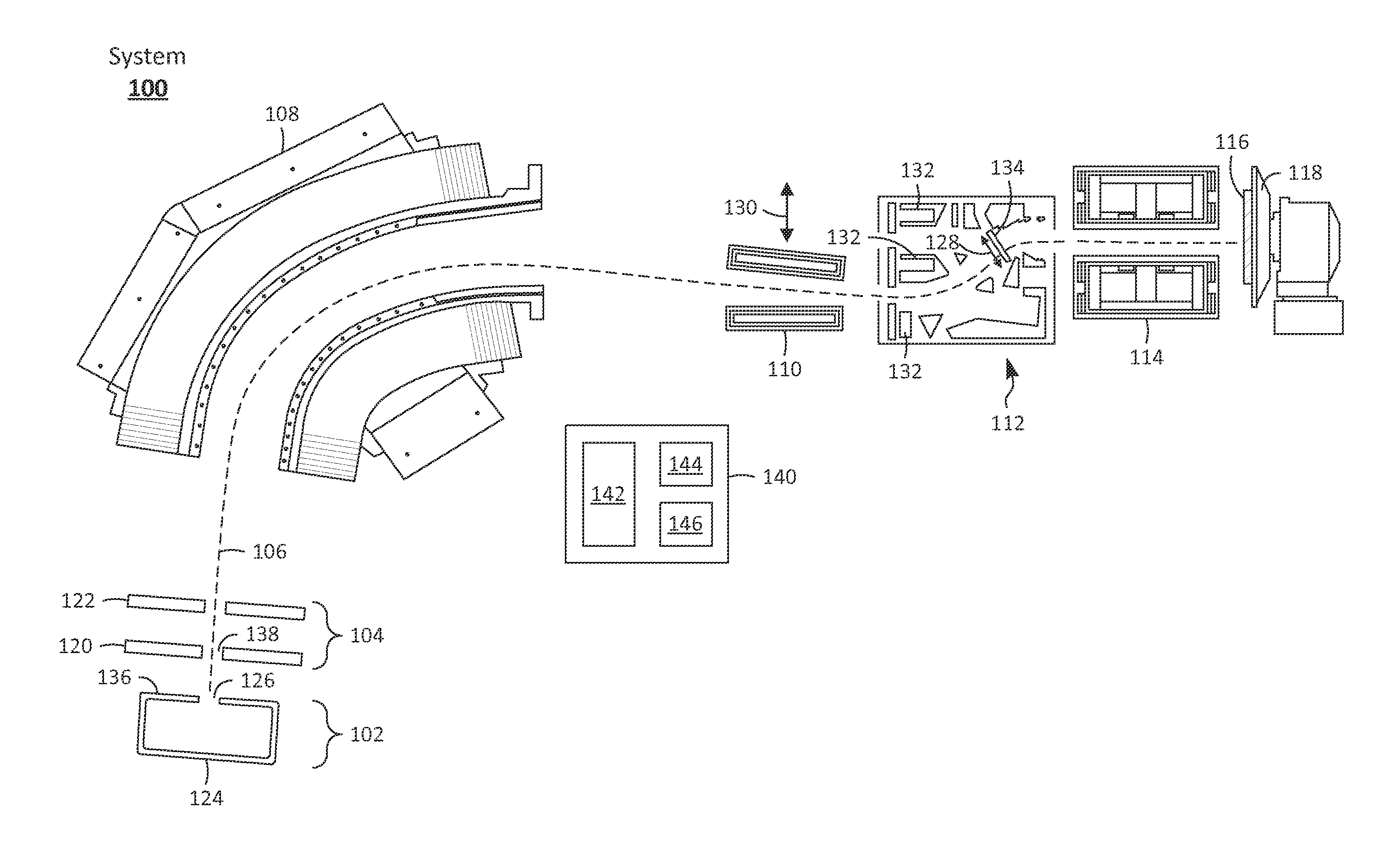
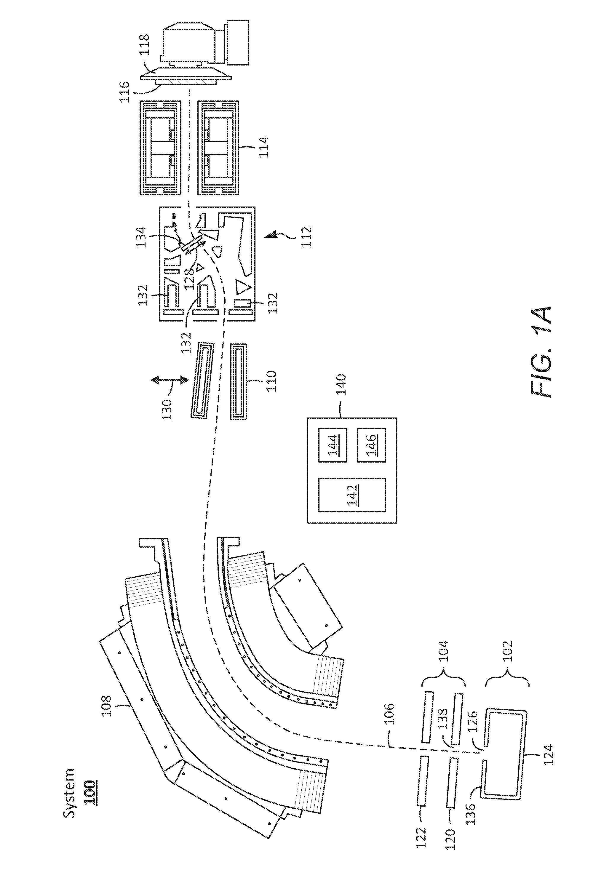
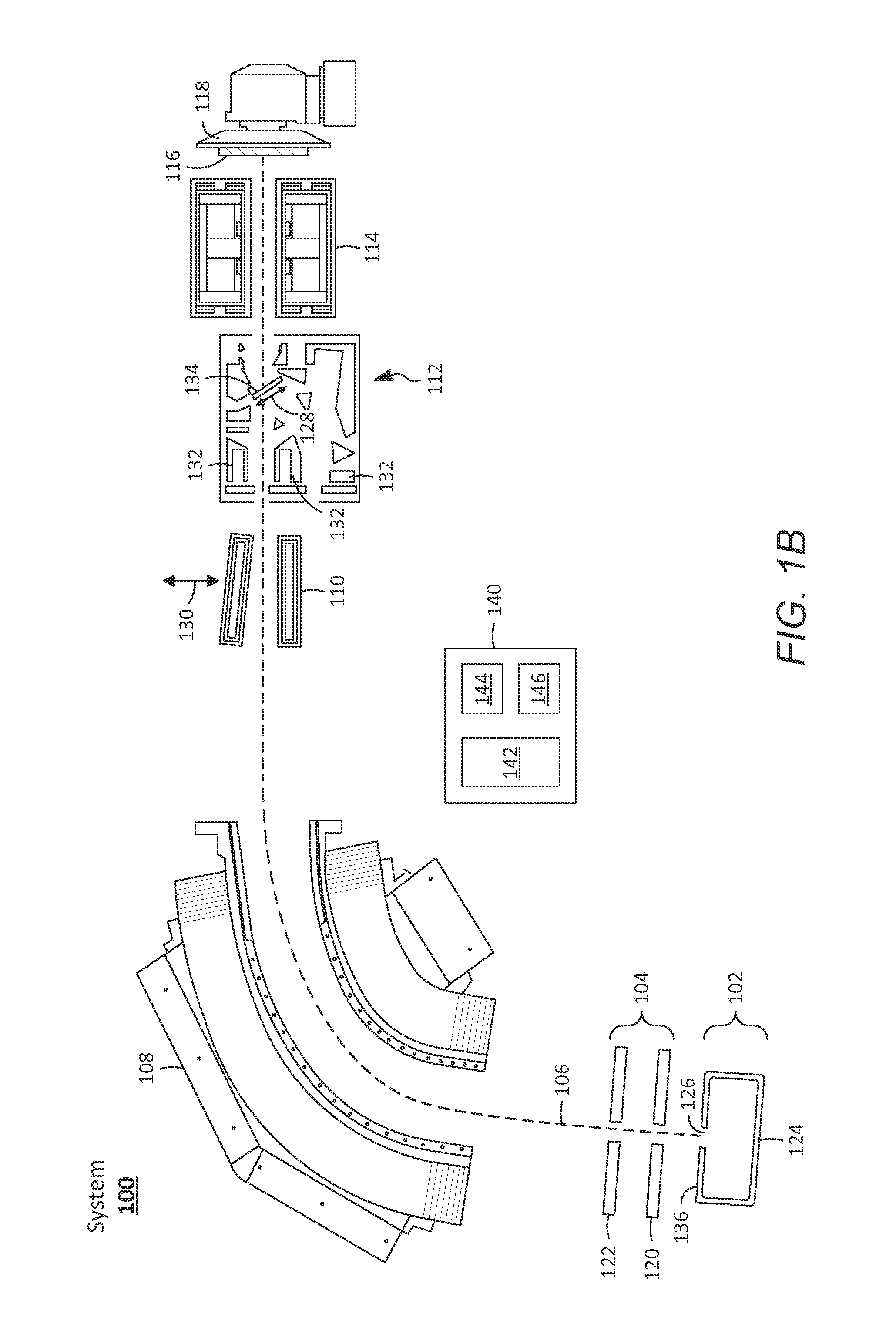
[0015]The present disclosure relates to systems and processes for lower dose rate ion implantation using a wider ion beam. In one example process, an ion beam may be generated using an ion source and an extraction manipulator. The extraction manipulator may be positioned from an exit aperture of the ion source at ...


PUM


Abstract

In an exemplary process for lower dose rate ion implantation of a work piece, an ion beam may be generated using an ion source and an extraction manipulator. The extraction manipulator may be positioned at a gap distance from an exit aperture of the ion source. A current of the ion beam exiting the extraction manipulator may be maximized when the extraction manipulator is positioned at an optimal gap distance from the exit aperture. The gap distance at which the extraction manipulator is positioned from the exit aperture may differ from the optimal gap distance by at least 10 percent. A first potential may be applied to a first set of electrodes. An x-dimension of the ion beam may increase as the ion beam passes through the first set of electrodes. The work piece may be positioned in the ion beam to implant ions into the work piece.

Description

BACKGROUND[0001]1. Field[0002]The present disclosure relates generally to ion implantation and, more specifically, to lower dose rate ion implantation using a wider ion beam.[0003]2. Related Art[0004]Ion implantation is a process used in fabricating integrated semiconductor devices whereby impurities are introduced into a work piece. During ion implantation, an ion beam may be extracted from an ion source and filtered by mass, charge, and energy through a magnetic analyzer before being directed to the work piece. In conventional ion implantation processes, the ion beam may typically be optimized to maximize the beam density, thereby maximizing dose rates and enabling higher throughput. For example, the ion beam may be extracted from the ion source under conditions that maximize the ion beam current. Further, the ion beam may be shaped and focused to form a narrow concentrated ribbon-shaped beam having high beam density.[0005]As semiconductor manufacturers continue to shrink the dime...

Claims


Application Information

Patent Timeline
IPC IPC(8): H01L21/265
CPCH01L21/265H01J37/08H01J37/3171H01J2237/024H01J2237/0835H01J2237/303H01J2237/30477
Inventor WAN, ZHIMINPADMANABHAN, REKHABAI, XIAOCAI, GARY N.LI, CHING-ILIN, GER-PINHU, SHAO-YUHOGLUND, DAVIDKAIM, ROBERT E.SAADATMAND, KOUROSH
Owner ADVANCED ION BEAM TECHNOLOGY INC
Why Eureka
Try Eureka