
Apparatus for limiting current of line or breaking current, and control method thereof

a technology of limiting current and line or breaking current, which is applied in the direction of emergency protective arrangements for limiting excess voltage/current, protective switch details, operating/releasing mechanisms of protective switches, etc., can solve the problems of high-voltage dc circuit breakers that require a long arc-extinguishing time, break currents in two directions, and small loss during normal operation, so as to reduce the difficulty of device layout, reduce the cost of the apparatus, and reduce the effect of high breaking speed

Active Publication Date: 2015-12-24
NR ELECTRIC CO LTD +1
View PDF5 Cites 10 Cited by
  • Summary
  • Abstract
  • Description
  • Claims
  • Application Information

AI Technical Summary

Benefits of technology

The present invention provides an apparatus and control method for limiting or breaking currents in two directions that are suitable for high-speed operation, with low loss and reduced costs. The apparatus includes a current breaking branch and a current commutation branch, with a small number of power semiconductor devices that can be turned on or off to control the current flow. The current breaking branch is formed by power switch devices connected in series in a same current direction, and the current commutation branch causes currents of the line that are in two directions to flow through the current breaking branch in a same direction. The apparatus has low conduction loss, reduces the difficulties in device layout, installation, and wiring, and achieves bidirectional current breaking at low costs. The high-speed isolation switches provide good isolation and maintenance function and significantly reduce the costs compared to other solutions.

Problems solved by technology

Such a breaking method does not include a power semiconductor device, is not directional, and therefore can break currents in two directions, and has a small loss during, normal operation.
However, the conventional high-voltage DC circuit breaker requires a long arc-extinguishing time of about a few tens of milliseconds, and cannot meet the requirement for quick fault isolation in the multi-end DC power transmission system.
When the current is broken in a first current direction, the power semiconductor devices in a second current direction do not have any beneficial effect to break the current or bear the voltage, that is, the utilization rate of the power semiconductor devices of the primary circuit breaker is only 50%.
As the costs of the power semiconductor devices account for a large proportion of the total costs of the apparatus, providing the function of breaking currents in two directions will greatly increase the costs of the apparatus.
The arrangement of the power semiconductor devices in the second current direction in the primary circuit breaker does not have any beneficial effect, and over-voltage and over-current generated When the current is turned off in the first current direction have adverse effects on the power semiconductor devices in the second current direction.
If the power semiconductor devices in the second current direction and the power semiconductor devices in the first current direction are connected in an anti-parallel manner, an over-voltage generated when the current is turned off in the first current direction will be applied to the power semiconductor devices in the second current direction, and the voltage is a reverse voltage for the power semiconductor devices in the second current direction and will cause damage to the devices; if the power semiconductor devices with anti-parallel diodes in the second current direction and the power semiconductor devices with anti-parallel diodes in the first current direction are connected in an anti-series manner, an abruptly increased current generated when the current is turned off in the first current direction will flow through free-wheeling diodes in the power semiconductor devices in the second current direction, reducing the service life of the devices.
The arrangement of the power semiconductor devices in the second current direction also has an adverse effect on the structural design and electrical design of the primary circuit breaker.
The arrangement of the power semiconductor devices in the second current direction destroys the original consistency in the arrangement direction, increasing the difficulty in device layout, installation and wiring.
CN102687221A, the ultra-high-speed mechanical switch is connected in parallel to the primary circuit breaker, the ultra-high-speed mechanical switch cannot completely isolate the apparatus to protect the primary circuit breaker, and the primary circuit breaker does not have obvious breakpoints and is difficult to repair and maintain.

Method used


Image

  • Apparatus for limiting current of line or breaking current, and control method thereof
  • Apparatus for limiting current of line or breaking current, and control method thereof
  • Apparatus for limiting current of line or breaking current, and control method thereof

Examples


Embodiment Construction

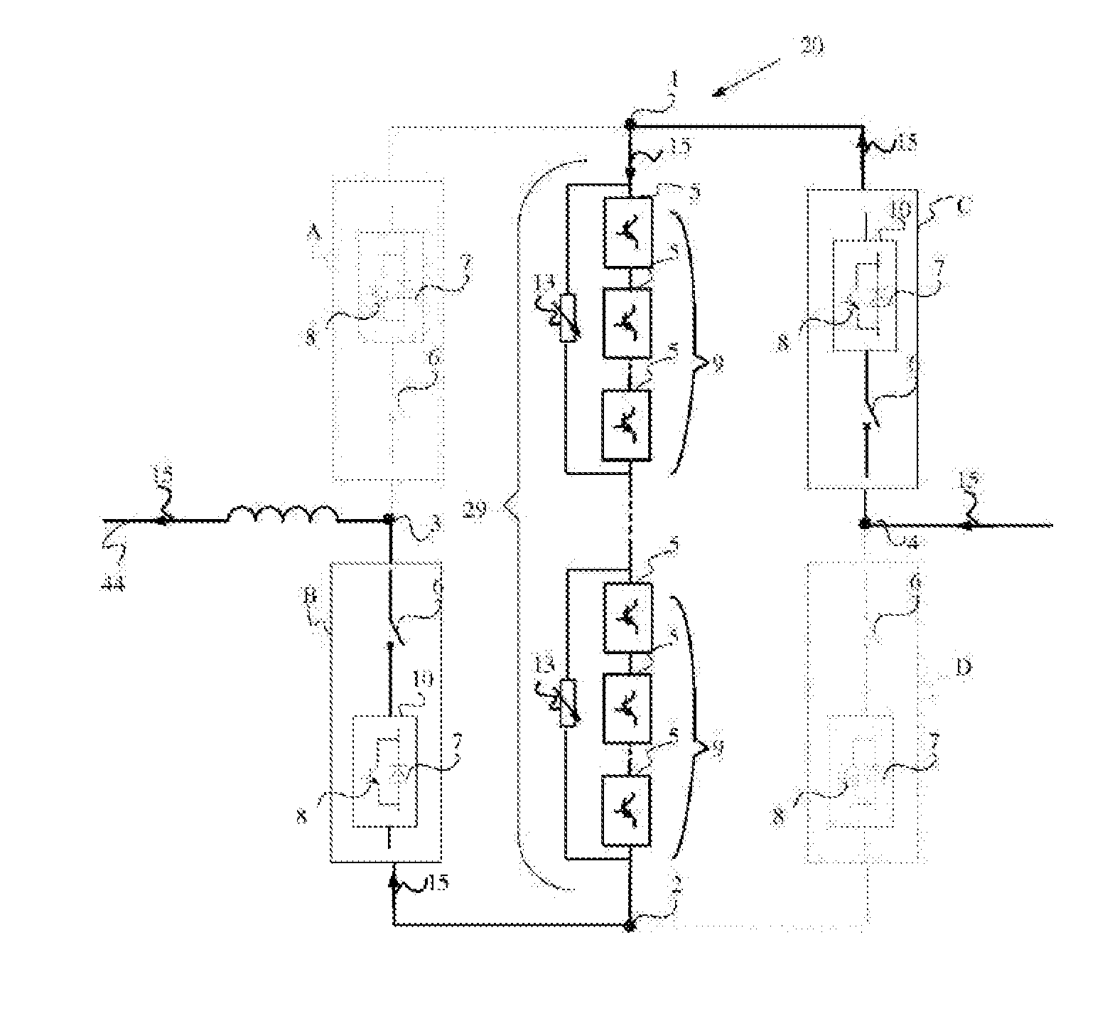
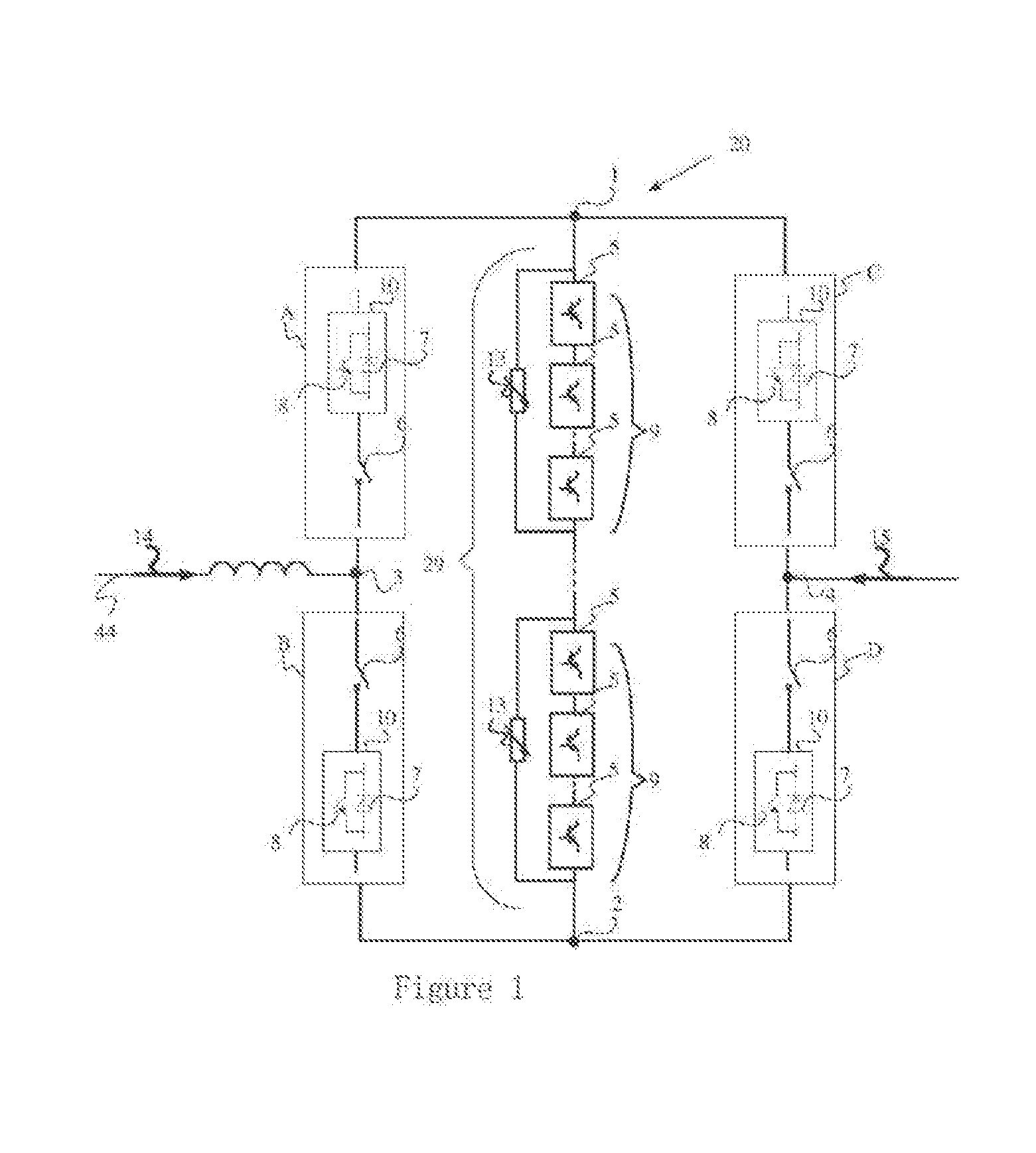
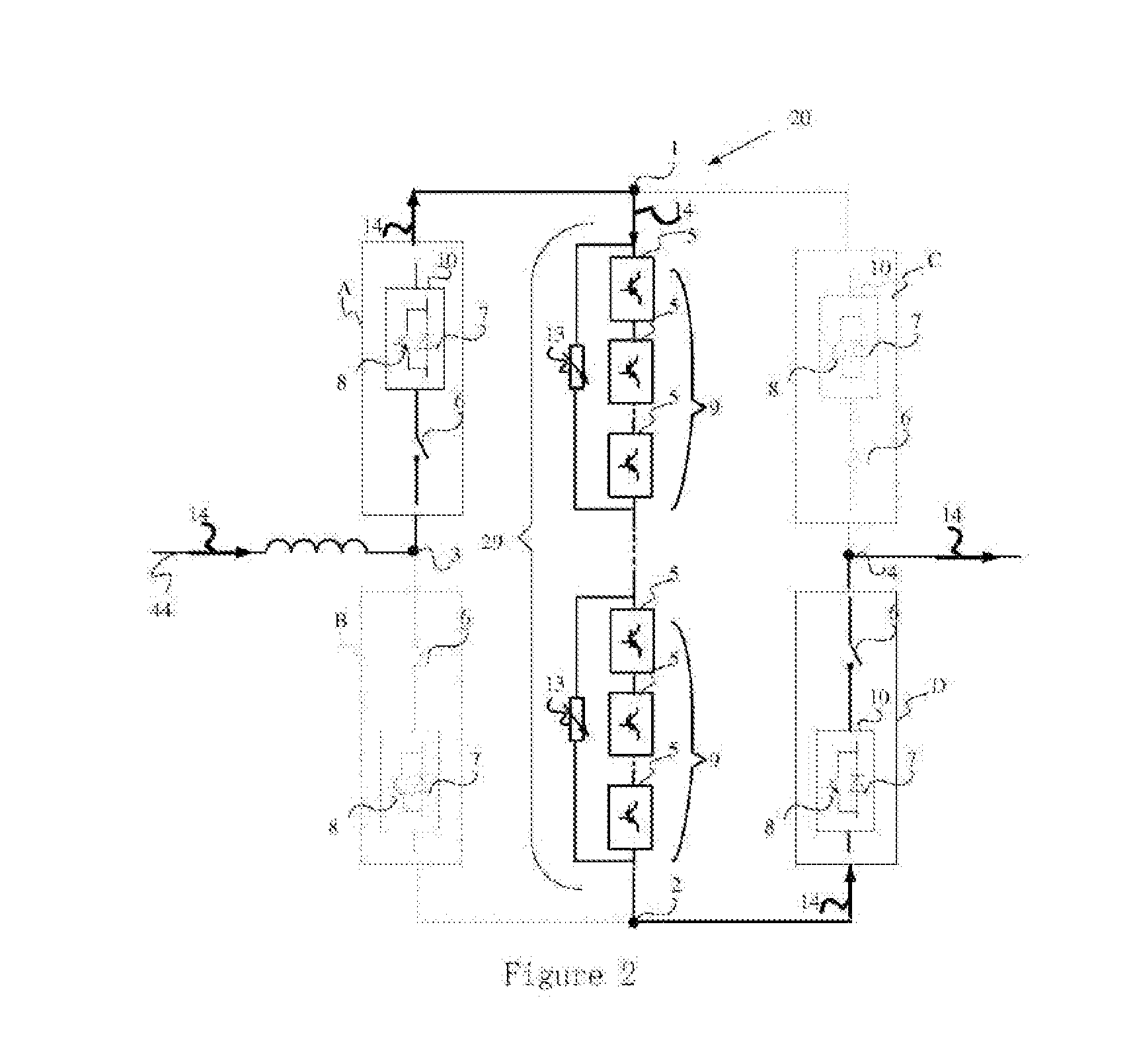
[0047]As shown in FIG. 1, an apparatus 20 for limiting a current of a line 44 or breaking a current according to the present invention includes a current breaking branch 29 and a bridge branch, which will be described below respectively.

[0048]The current breaking branch 29 includes at least one breaking unit connected in series, and two ends of the current breaking branch 29 are a node1 and a node 2 respectively. Each breaking unit includes one solid-state DC circuit breaker 9 and one non-linear resistance 13 connected in parallel, the solid-state DC circuit breaker 9 is formed by at least one power semiconductor device 5 connected in series, and an arrangement direction of the solid-state DC circuit breaker 9 is the same as a current direction from the node 1 to the node 2.

[0049]The bridge branch includes two bridge anus formed by four identical current commutation branches A, B, C, and D, where a specific relationship of connection is that: the current commutation branches A and B...


PUM


Abstract

An apparatus for limiting a current of a line or breaking a current, and a control method thereof are disclosed. The apparatus includes a current breaking branch (29) and a bridge branch. The bridge branch includes two bridge arms formed by four identical current commutation branches. Every two of the four current commutation branches are connected in series, and the formed two bridge arms are then connected in parallel. The two bridge arms are both connected in parallel to the current breaking branch, and middle points of the two bridge arms are separately connected to two ends of a line. Each current commutation branch includes at least one high-speed isolation switch (6) and at least one bidirectional power semiconductor switch (10) that are connected in series. The apparatus can turn off currents in two directions.

Description

TECHNICAL FILED OF THE INVENTION[0001]The present invention relates to an apparatus for limiting a current of a line or breaking a current of a line, and a method for controlling the apparatus.BACKGROUND[0002]High-voltage direct current (DC) circuit breaker is one of crucial devices in multi-end. DC power transmission systems. A multi-end high-voltage DC power transmission system has a high voltage level and small line impedance, and once a line short-circuit fault occurs, a DC power transmission network and an alternating current (AC) network will be momentarily affected, therefore, the fault must be cleared quickly. Therefore, a high-voltage DC circuit breaker needs to act as quickly as possible to shorten the duration of the fault or suppress the fault current to the greatest extent, so as to reduce the impacts of the fault on the AC / DC power transmission network. Because the high-voltage DC circuit breaker is connected in series in the power transmission line, the power flow dir...

Claims


Application Information

Patent Timeline
IPC IPC(8): H02H3/08H02H9/02H01H71/10
CPCH01H71/1045H02H3/08H02H9/02H01H2009/0083H01H9/548H01H33/596H01H9/542
Inventor WANG, YUCAO, DONGMINGFANG, TAIXUNYANG, HAOYANG, BINGSHI, WEILU, WEI
Owner NR ELECTRIC CO LTD
Learn More